It’s been coming for a while: The requirement to deploy VMs with a TPM module… Today I’ll be showing you the easiest and quickest way to create and deploy Virtual Machines with vTPM on VMware vSphere ESXi!
As most of you know, Windows 11 has a requirement for Secureboot as well as a TPM module. It’s with no doubt that we’ll also possibly see this requirement with future Microsoft Windows Server operating systems.
While users struggle to deploy TPM modules on their own workstations to be eligible for the Windows 11 upgrade, ESXi administrators are also struggling with deploying Virtual TPM modules, or vTPM modules on their virtualized infrastructure.
What is a TPM Module?
TPM stands for Trusted Platform Module. A Trusted Platform Module, is a piece of hardware (or chip) inside or outside of your computer that provides secured computing features to the computer, system, or server that it’s attached to.
This TPM modules provides things like a random number generator, storage of encryption keys and cryptographic information, as well as aiding in secure authentication of the host system.
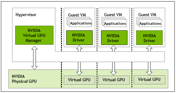
In a virtualization environment, we need to emulate this physical device with a Virtual TPM module, or vTPM.
What is a Virtual TPM (vTPM) Module?
A vTPM module is a virtualized software instance of a traditional physical TPM module. A vTPM can be attached to Virtual Machines and provide the same features and functionality that a physical TPM module would provide to a physical system.
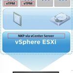
vTPM modules can be can be deployed with VMware vSphere ESXi, and can be used to deploy Windows 11 on ESXi.
Deployment of vTPM modules, require a Key Provider on the vCenter Server.
Deploying vTPM (Virtual TPM Modules) on VMware vSphere ESXi
In order to deploy vTPM modules (and VM encryption, vSAN Encryption) on VMware vSphere ESXi, you need to configure a Key Provider on your vCenter Server.
Traditionally, this would be accomplished with a Standard Key Provider utilizing a Key Management Server (KMS), however this required a 3rd party KMS server and is what I would consider a complex deployment.
VMware has made this easy as of vSphere 7 Update 2 (7U2), with the Native Key Provider (NKP) on the vCenter Server.
The Native Key Provider, allows you to easily deploy technologies such as vTPM modules, VM encryption, vSAN encryption, and the best part is, it’s all built in to vCenter Server.
Enabling VMware Native Key Provider (NKP)
To enable NKP across your vSphere infrastructure:
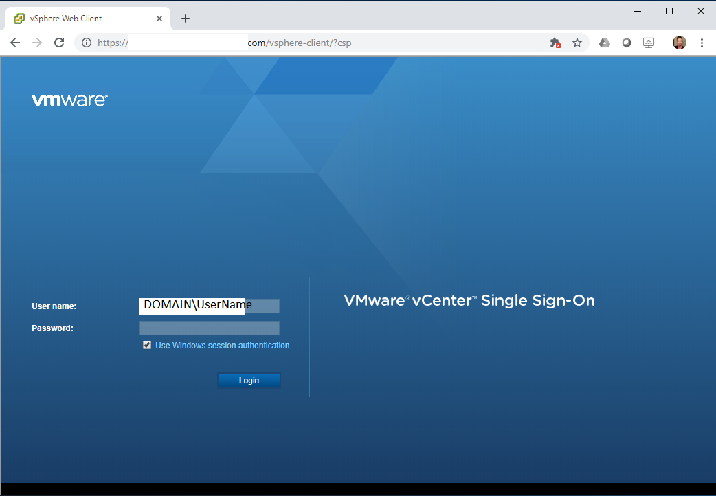
Log on to your vCenter Server
Select your vCenter Server from the Inventory List
Select “Key Providers”
Click on “Add”, and select “Add Native Key Provider”
Give the new NKP a friendly name
De-select “Use key provider only with TPM protected ESXi hosts” to allow your ESXi hosts without a TPM to be able to use the native key provider.
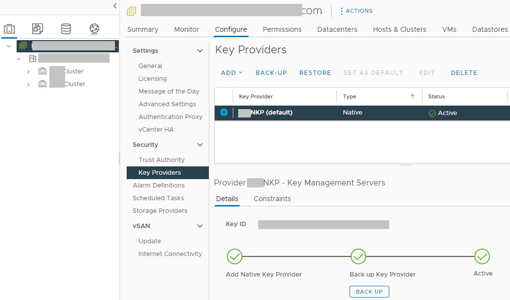
In order to activate your new native key provider, you need to click on “Backup” to make sure you have it backed up. Keep this backup in a safe place. After the backup is complete, you NKP will be active and usable by your ESXi hosts.
VMware vCenter with Native Key Provider (NKP) Configured
There’s a few additional things to note:
Your ESXi hosts do NOT require a physical TPM module in order to use the Native Key Provider
Just make sure you disable the checkbox “Use key provider only with TPM protected ESXi hosts”
NKP can be used to enable vTPM modules on all editions of vSphere
If your ESXi hosts have a TPM module, using the Native Key Provider with your hosts TPM modules can provide enhanced security
Onboard TPM module allows keys to be stored and used if the vCenter server goes offline
If you delete the Native Key Provider, you are also deleting all the keys stored with it.
Make sure you have it backed up
Make sure you don’t have any hosts/VMs using the NKP before deleting
You can now deploy vTPM modules to virtual machines in your VMware environment.
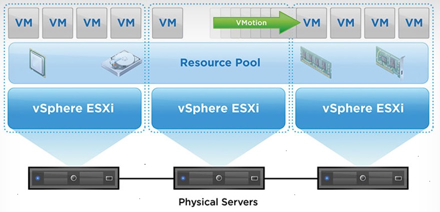
We all know that vMotion is awesome, but what is even more awesome? Optimizing VMware vMotion to make it redundant and faster!
vMotion allows us to migrate live Virtual Machines from one ESXi host to another without any downtime. This allows us to perform physical maintenance on the ESXi hosts, update and restart the hosts, and also load balance VMs across the hosts. We can even take this a step further use DRS (Distributed Resource Scheduler) automation to intelligently load the hosts on VM boot and to dynamically load balance the VMs as they run.
VMware vMotion
In this post, I’m hoping to provide information on how to fully optimize and use vMotion to it’s full potential.
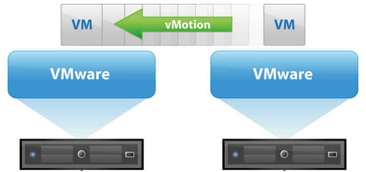
VMware vMotion
Most of you are probably running vMotion in your environment, whether it’s a homelab, dev environment, or production environment.
I typically see vMotion deployed on the existing data network in smaller environments, I see it deployed on it’s own network in larger environments, and in very highly configured environments I see it being used with the vMotion TCP stack.
While you can preform a vMotion with 1Gb networking, you certainly almost always want at least 10Gb networking for the vMotion network, to avoid any long running VMs. Typically most IT admins are happy with live migration vMotion’s in the seconds, and not the minutes.
VMware vMotion Optimization
So you might ask, if vMotion is working and you’re satisfied, what is there to optimize? There’s actually a few things, but first let’s talk about what we can improve on.
We’re aiming for improvements with:
Throughput/Speed
Faster vMotion
Faster Speed
Less Time
Migrate more VMs
Evacuate hosts faster
Enable more aggressive DRS
Migrate many VMs at once very quickly
Redundancy
Redundant vMotion Interfaces (NICs and Uplinks)
More Complex vMotion Configurations
vMotion over different subnets and VLANs
vMotion routed over Layer 3 networks
To achieve the above, we can focus on the following optimizations:
Enable Jumbo Frames
Saturation of NIC/Uplink for vMotion
Multi-NIC/Uplink vMotion
Use of the vMotion TCP Stack
Let’s get to it!
Enable Jumbo Frames
I can’t stress enough how important it is to use Jumbo Frames for specialized network traffic on high speed network links. I highly recommend you enable Jumbo Frames on your vMotion network.
Note, that you’ll need to have a physical switch and NICs that supports Jumbo frames.
In my own high throughput testing on a 10Gb link, without using Jumbo frames I was only able to achieve transfer speeds of ~6.7Gbps, whereas enabling Jumbo Frames allowed me to achieve speeds of ~9.8Gbps.
When enabling this inside of vSphere and/or ESXi, you’ll need to make sure you change and update the applicable vmk adapter, vSwitch/vDS switches, and port groups. Additionally as mentioned above you’ll need to enable it on your physical switches.
Saturation NIC/Uplink for vMotion
You may assume that once you configure a vMotion enabled NIC, that when performing migrations you will be able to fully saturate it. This is not necessarily the case!
When performing a vMotion, the vmk adapter is bound to a single thread (or CPU core). Depending on the power of your processor and the speed of the NIC, you may not actually be able to fully saturate a single 10Gb uplink.
In my own testing in my homelab, I needed to have a total of 2 VMK adapters to saturate a single 10Gb link.
If you’re running 40Gb or even 100Gb, you definitely want to look at adding multiple VMK adapters to your vMotion network to be able to fully saturate a single NIC or Uplink.
You can do this by simply configuring multiple VMK adapters per host with different IP addresses on the same subnet.
One important thing to mention is that if you have multiple physical NICs and Uplinks connected to your vMotion switch, this change will not help you utilize multiple physical interfaces (NICs/Uplinks). See “Multi-NIC/Uplink vMotion”.
Please note: As of VMware vSphere 7 Update 2, the above is not required as vMotion has been optimized to use multiple streams to fully saturate the interface. See VMware’s blog post “Faster vMotion Makes Balancing Workloads Invisible” for more information.
Multi-NIC/Uplink vMotion
Another situation is where we may want to utilize multiple NICs and Uplinks for vMotion. When implemented correctly, this can provide load balancing (additional throughput) as well as redundancy on the vMotion network.
If you were to simply add additional NIC interfaces as Uplinks to your vMotion network, this would add redundancy in the event of a failover but it wouldn’t actually result in increased speed or throughput as special configuration is required.
To take advantage of the additional bandwidth made available by additional Uplinks, we need to specially configure multiple portgroups on the switch (vSwitch or vDS Distributed Switch), and configure each portgroup to only use one of the Uplinks as the “Active Uplink” with the rest of the uplinks under “Standby Uplink”.
Example Configuration
vSwitch or vDS Switch
Portgroup 1
Active Uplink: Uplink 1
Standby Uplinks: Uplink 2, Uplink 3, Uplink 4
Portgroup 2
Active Uplink: Uplink 2
Standby Uplinks: Uplink 1, Uplink 3, Uplink 4
Portgroup 3
Active Uplink: Uplink 3
Standby Uplinks: Uplink 1, Uplink 2, Uplink 4
Portgroup 4
Active Uplink: Uplink 4
Standby Uplinks: Uplink 1, Uplink 2, Uplink 3
You would then place a single or multiple vmk adapters on each of the portgroups per host, which would result in essentially mapping the vmk(s) to the specific uplink. This will allow you to utilize multiple NICs for vMotion.
And remember, you may not be able to fully saturate a NIC interface (as stated above) with a single vmk adapter, so I highly recommend creating multiple vmk adapters on each of the Port groups above to make sure that you’re not only using multiple NICs, but that you can also fully saturate each of the NICs.
VMware released the vMotion TCP Stack to provided added security to vMotion capabilities, as well as introduce vMotion over multiple subnets (routed vMotion over layer 3).
Using the vMotion TCP Stack, you can isolate and have the vMotion network using it’s own gateway separate from the other vmk adapters using the traditional TCP stack on the ESXi host.
When performing a VMware vMotion on a Virtual Machine with an NVIDIA vGPU attached to it, the VM may freeze during migration. Additionally, when performing a vMotion on a VM without a vGPU, the VM does not freeze during migration.
So why is it that adding a vGPU to a VM causes it to become frozen during vMotion? This is referred to as the VM Stun Time.
I’m going to explain why this happens, and what you can do to reduce these STUN times.
VMware vMotion
First, let’s start with traditional vMotion without a vGPU attached.
VMware vMotion with vSphere
vMotion allows us to live migrate a Virtual Machine instance from one ESXi host, to another, with (visibly) no downtime. You’ll notice that I put “visibly” in brackets…
When performing a vMotion, vSphere will migrate the VM’s memory from the source to destination host and create checkpoints. It will then continue to copy memory deltas including changes blocks after the initial copy.
Essentially vMotion copies the memory of the instance, then initiates more copies to copy over the changes after the original transfer was completed, until the point where it’s all copied and the instance is now running on the destination host.
VMware vMotion with vGPU
For some time, we have had the ability to perform a vMotion with a VM that as a GPU attached to it.
VMware VMs with vGPU
However, in this situation things work slightly different. When performing a vMotion, it’s not only the system RAM memory that needs to be transferred, but the GPU’s memory (VRAM) as well.
Unfortunately the checkpoint/delta transfer technology that’s used with then system RAM isn’t available to transfer the GPU, which means that the VM has to be stunned (frozen) to stop it so that the video RAM can be transferred and then the instance can be initialized on the destination host.
STUN Time
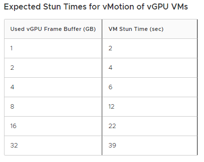
The STUN time is essentially the time it takes to transfer the video RAM (framebuffer) from one host to another.
When researching this, you may find examples of the time it takes to transfer various sizes of VRAM. An example would be from VMware’s documentation “Using vMotion to Migrate vGPU Virtual Machines“:
Expected STUN Times for vMotion with vGPU on 10Gig vMotion NIC
However, it will always vary depending on a number of factors. These factors include:
vMotion Network Speed
vMotion Network Optimization
Multi-NIC vMotion to utilize multiple NICs
Multi-vmk vMotion to optimize and saturate single NICs
Server Load
Network Throughput
The number of VM’s that are currently being migrated with vMotion
As you can see, there’s a number of things that play in to this. If you have a single 10Gig link for vMotion and you’re migrating many VMs with a vGPU, it’s obviously going to take longer than if you were just migrating a single VM with a vGPU.
Optimizing and Minimizing vGPU STUN Time
There’s a number of things we can look at to minimize the vGPU STUN times. This includes:
Upgrading networking throughput with faster NICs
Optimizing vMotion (Configure multiple vMotion VMK adapters to saturate a NIC)
All of the above can be implemented together, which I would actually recommend.
In short, the faster we migrate the VM, the less the STUN Time will be. Check out my blog post on Optimizing VMware vMotion which includes how to perform the above recommendations.
For over a year and a half I have been working on building a custom NVMe Storage Server for my homelab. I wanted to build a high speed storage system similar to a NAS or SAN, backed with NVMe drives that provides iSCSI, NFS, and SMB Windows File Shares to my network.
The computers accessing the NVMe Storage Server would include VMware ESXi hosts, Raspberry Pi SBCs, and of course Windows Computers and Workstations.
The focus of this project is on high throughput (in the GB/sec) and IOPS.
The current plan for the storage environment is for video editing, as well as VDI VM storage. This can and will change as the project progresses.
The History
More and more businesses are using all-flash NVMe and SSD based storage systems, so I figured there’s no reason why I can’t have build and have my own budget custom all NVMe flash NAS.
This is the story of how I built my own NVMe based Storage Server.
The first version of the NVMe Storage Server consisted of the IO-PEX40152 card with 4 x 2TB Sabrent Rocket 4 NVMe drives inside of an HPE Proliant DL360p Gen8 Server. The server was running ESXi with TrueNAS virtualized, and the PCIe card passed through to the TrueNAS VM.
The results were great, the performance was amazing, and both servers had access to the NFS export via 2 x 10Gb SFP+ networking.
There were three main problems with this setup:
Virtualized – Once a month I had an ESXi PSOD. This was either due to overheating of the IO-PEX40152 card because of modifications I made, or bugs with the DL360p servers and PCIe passthrough.
NFS instead of iSCSI – Because TrueNAS was virtualized inside of the host that was using it for storage, I had to use NFS since the host virtualizing TrueNAS would also be accessing the data on the TrueNAS VM. When shutting down the host, you need to shut down TrueNAS first. NFS disconnects are handled way healthier than iSCSI disconnects (which can cause corruption even if no files are being used).
CPU Cores maxed on data transfer – When doing initial testing, I was maxing out the CPU cores assigned to the TrueNAS VM because the data transfers were so high. I needed a CPU and setup that was better fit.
Version 1 went great, but you can see some things needed to be changed. I decided to go with a dedicated server, not virtualize TrueNAS, and go for a newer CPU with a higher Ghz speed.
And so, version 2 was born (built). Keep reading and scrolling for pictures!
The Hardware
On version 2 of the project, the hardware includes:
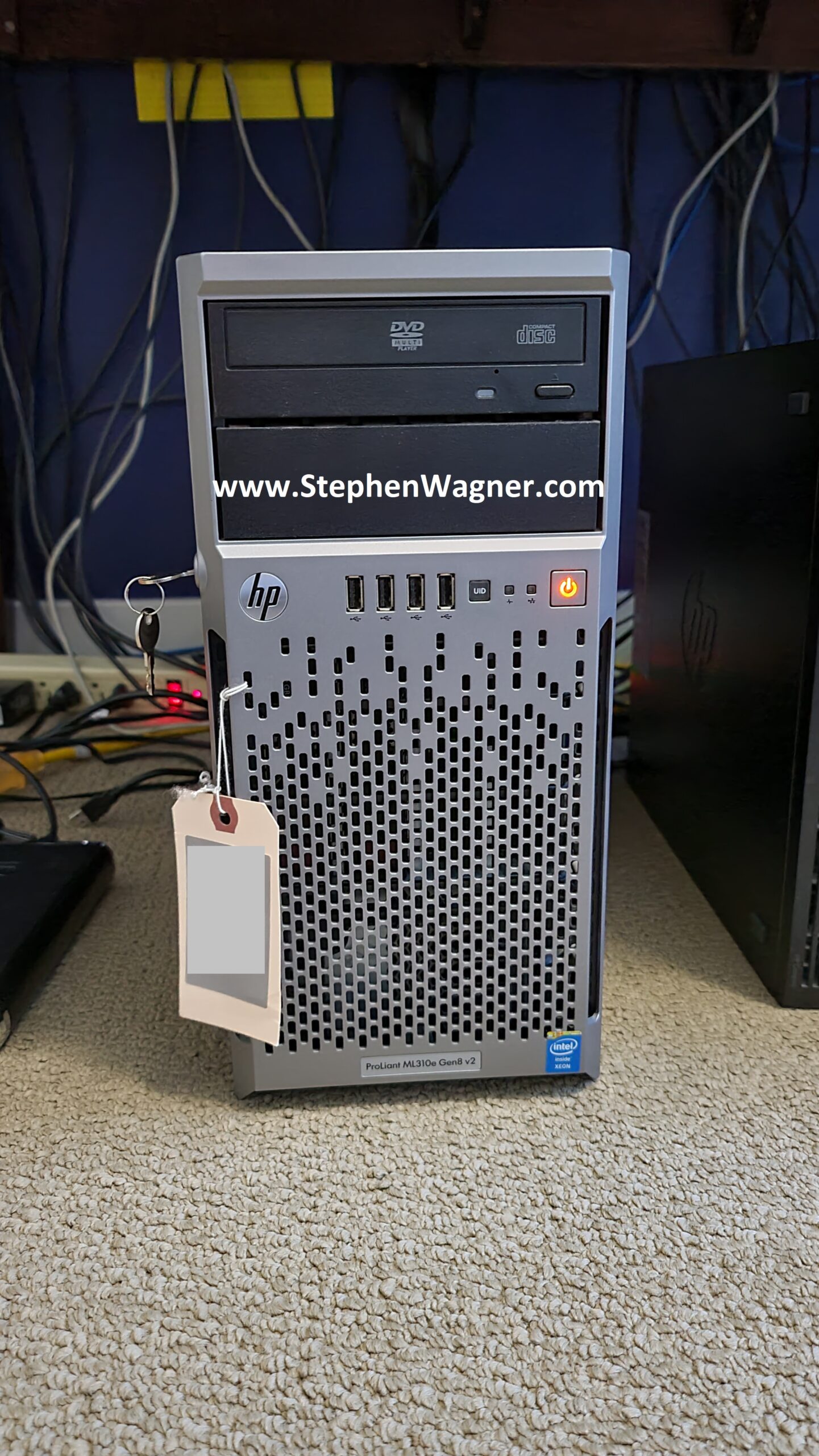
While the ML310e Gen8 v2 server is a cheap low entry server, it’s been a fantastic team member of my homelab.
HPE Dual 10G Port 560SFP+ adapters can be found brand new in unsealed boxes on eBay at very attractive prices. Using HPE Parts inside of HPE Servers, avoids the fans from spinning up fast.
The ML310e Gen8 v2 has some issues with passing through PCIe cards to ESXi. Works perfect when not passing through.
The new NVMe Storage Server
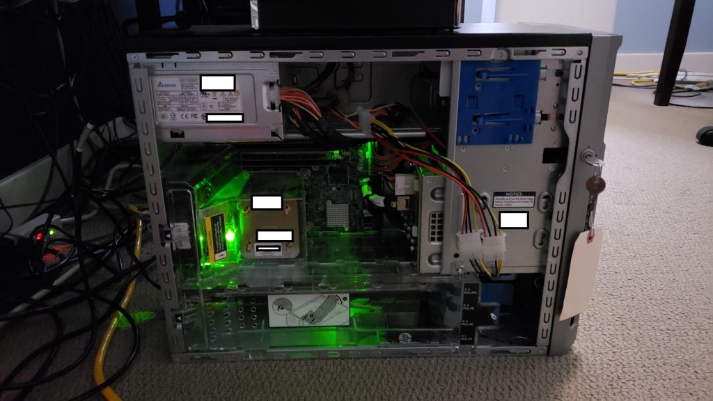
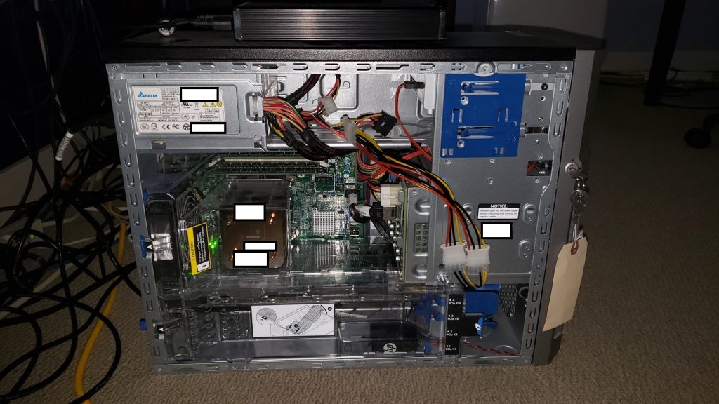
I decided to repurpose an HPE Proliant ML310e Gen8 v2 Server. This server was originally acting as my Nvidia Grid K1 VDI server, because it supported large PCIe cards. With the addition of my new AMD S7150 x2 hacked in/on to one of my DL360p Gen8’s, I no longer needed the GRID card in this server and decided to repurpose it.
HPe ML310e Gen8 v2 with NVMe Storage
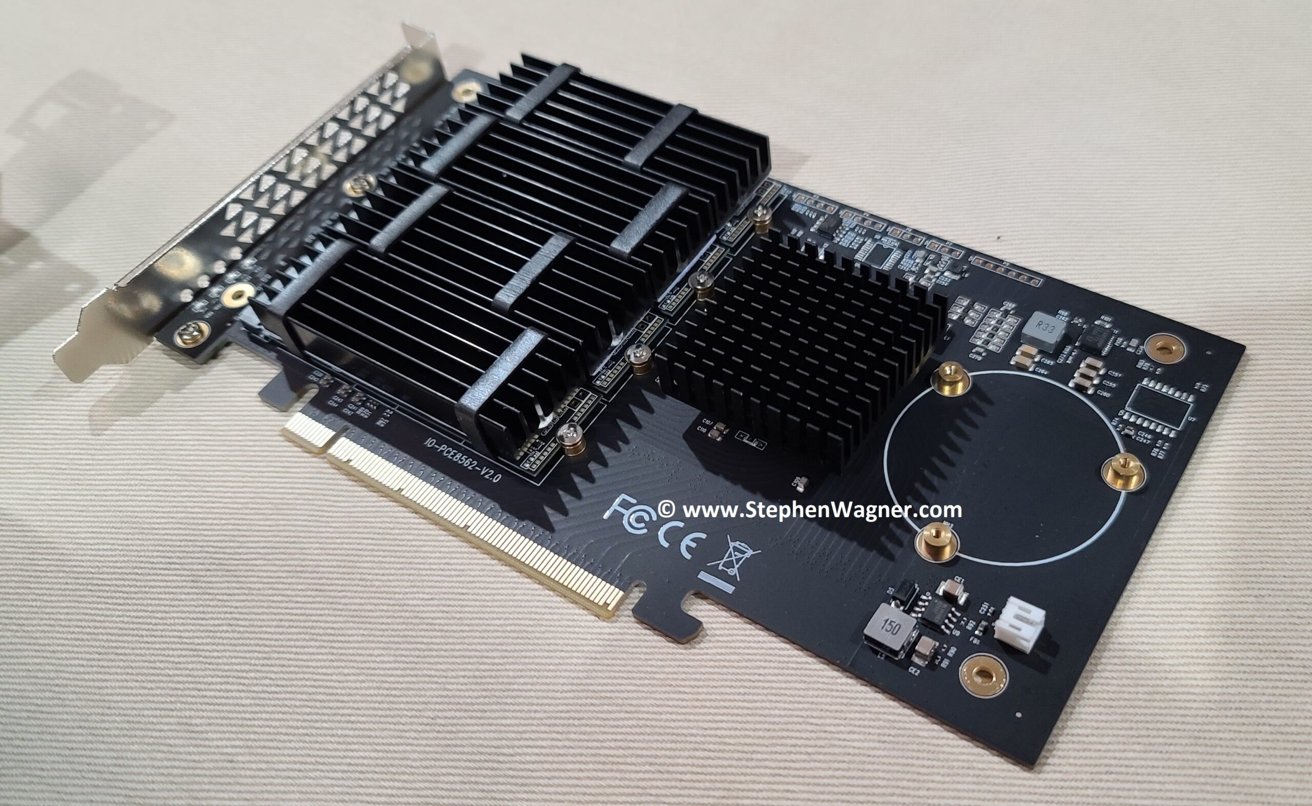
I installed the IOCREST IO-PEX40152 card in to the PCIe 16x slot, with 4 x 2TB Sabrent Rocket 4 NVME drives.
IOCREST IO-PEX40152 with GLOTRENDS M.2 NVMe SSD Heatsink on Sabrent Rocket 4 NVME
While the server has a PCIe 16x wide slot, it only has an 8x bus going to the slot. This means we will have half the capable speed vs the true 16x slot. This however does not pose a problem because we’ll be maxing out the 10Gb NICs long before we max out the 8x bus speed.
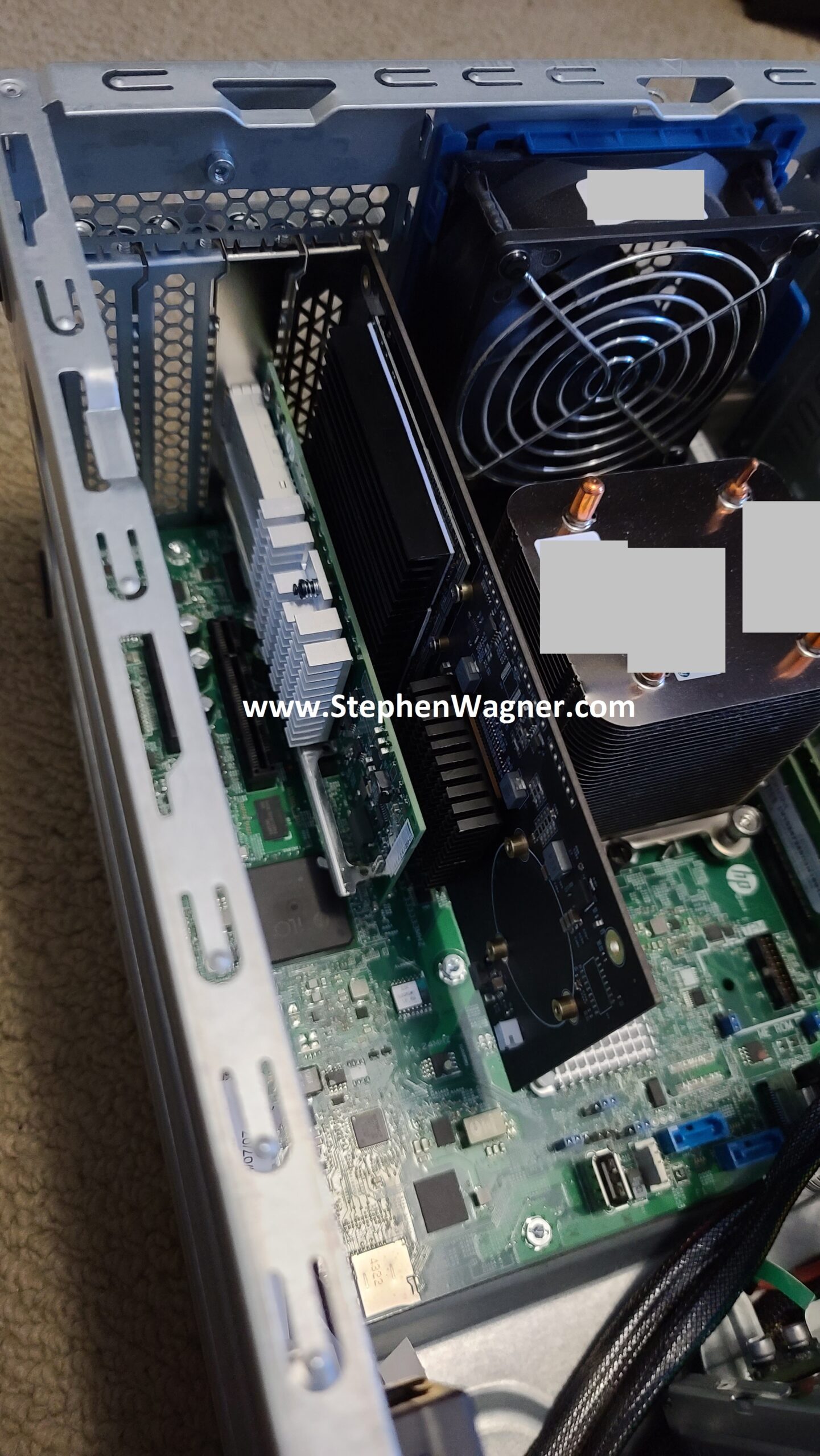
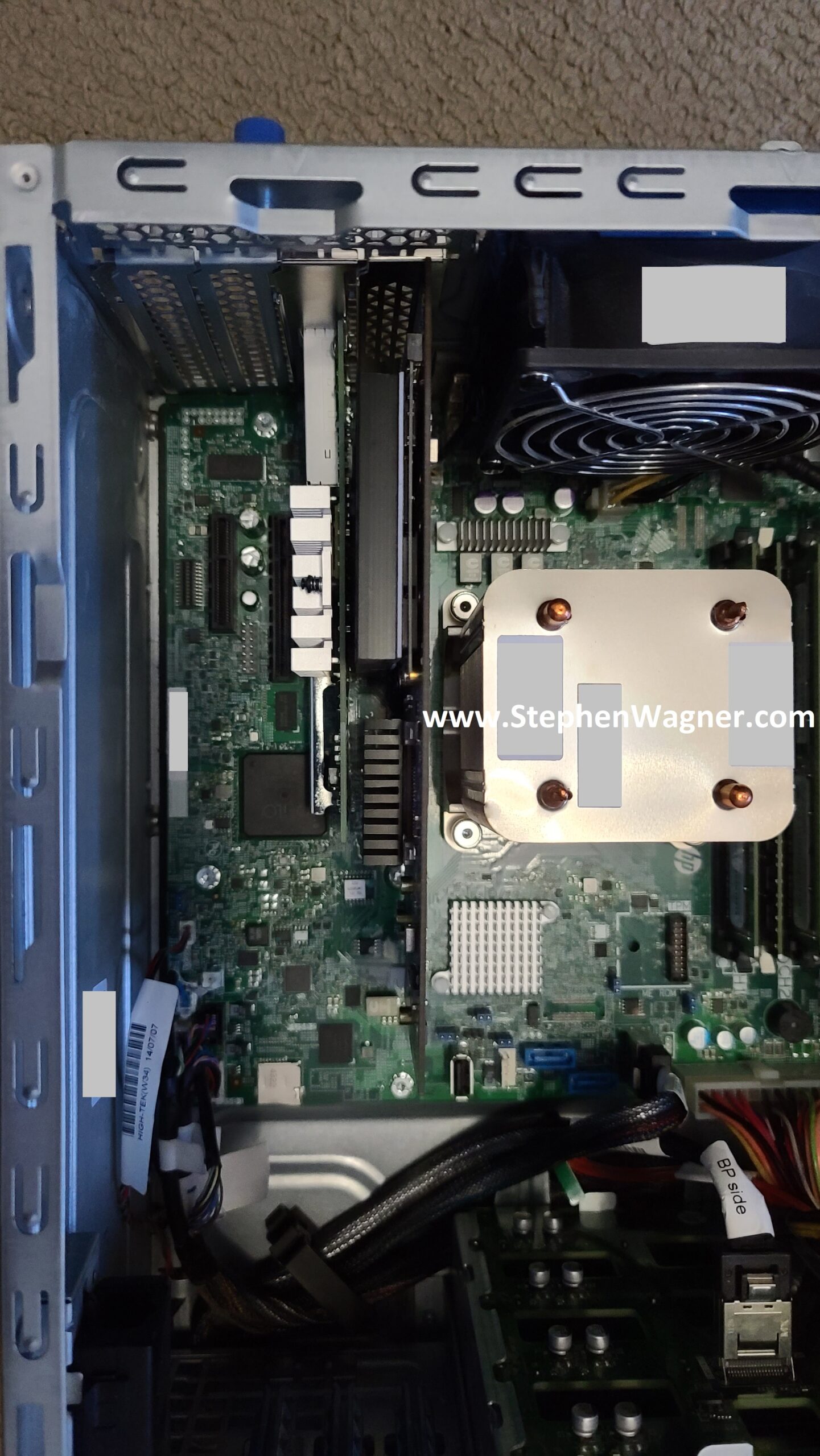
HPE ML310e Gen8 v2 with IOCREST IO-PEX40152HPE ML310e Gen8 v2 with IOCREST IO-PEX40152
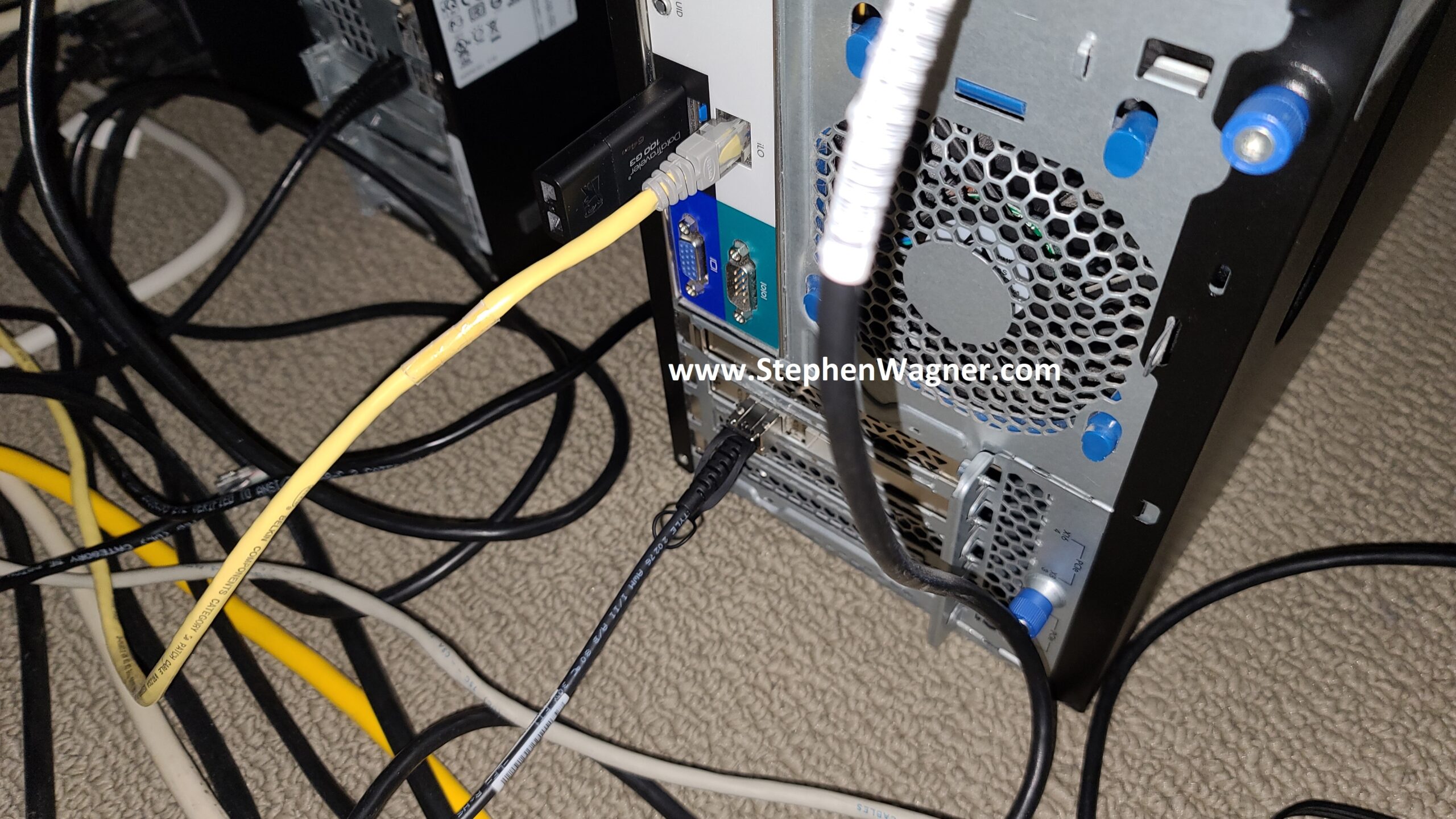
I also installed an HPE Dual Port 560SFP+ NIC in to the second slot. This will allow a total of 2 x 10Gb network connections from the server to the Ubiquiti UniFi US-16-XG 10Gb network switch, the backbone of my network.
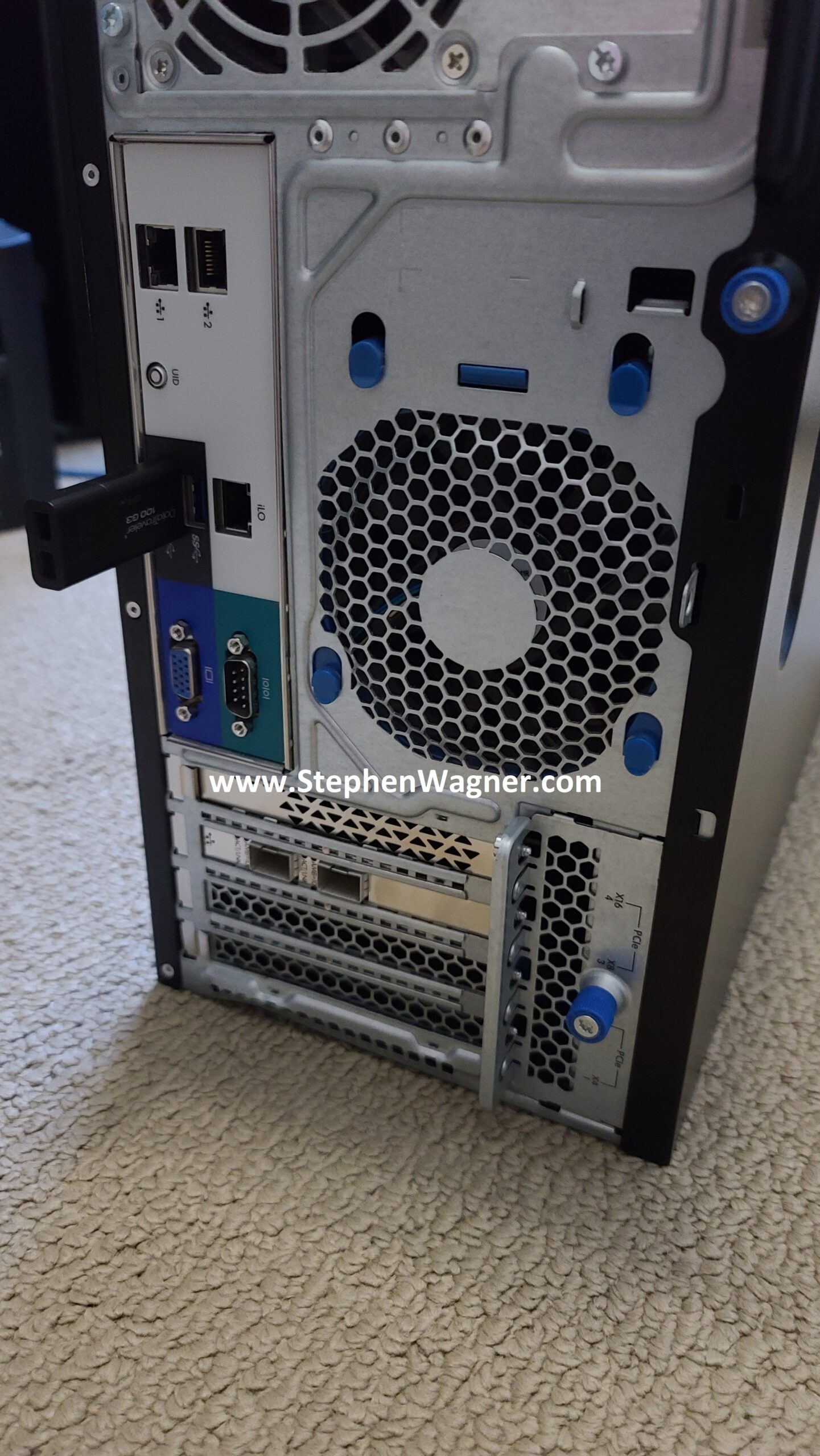
HPE ML310e Gen8 v2 with HPE 560SFP+ and 10Gig DACHPE ML310e Gen8 v2 with HPE 560SFP+ and 10Gig DAC
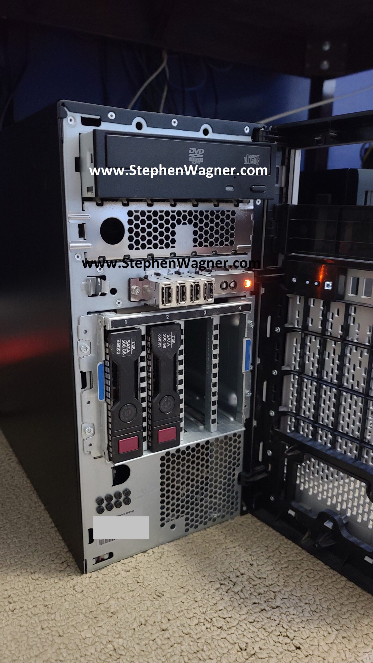
The Server also have 4 x Hot Swappable HD bays on the front. When configured in HBA mode (via the BIOS), these are accessible by TrueNAS and can be used. I plan on populating these with 4 x 4TB HPE MDL SATA Hot Swappable drives to act as a replication destination for the NVMe pool and/or slower magnetic long-term storage.
HPE ML310e Gen8 v2 with Hotswap Drive bays
I may also try to give WD RED Pro drives a try, but I’m not sure if they will cause the fans to speed up on the server.
TrueNAS Installation and Configuration
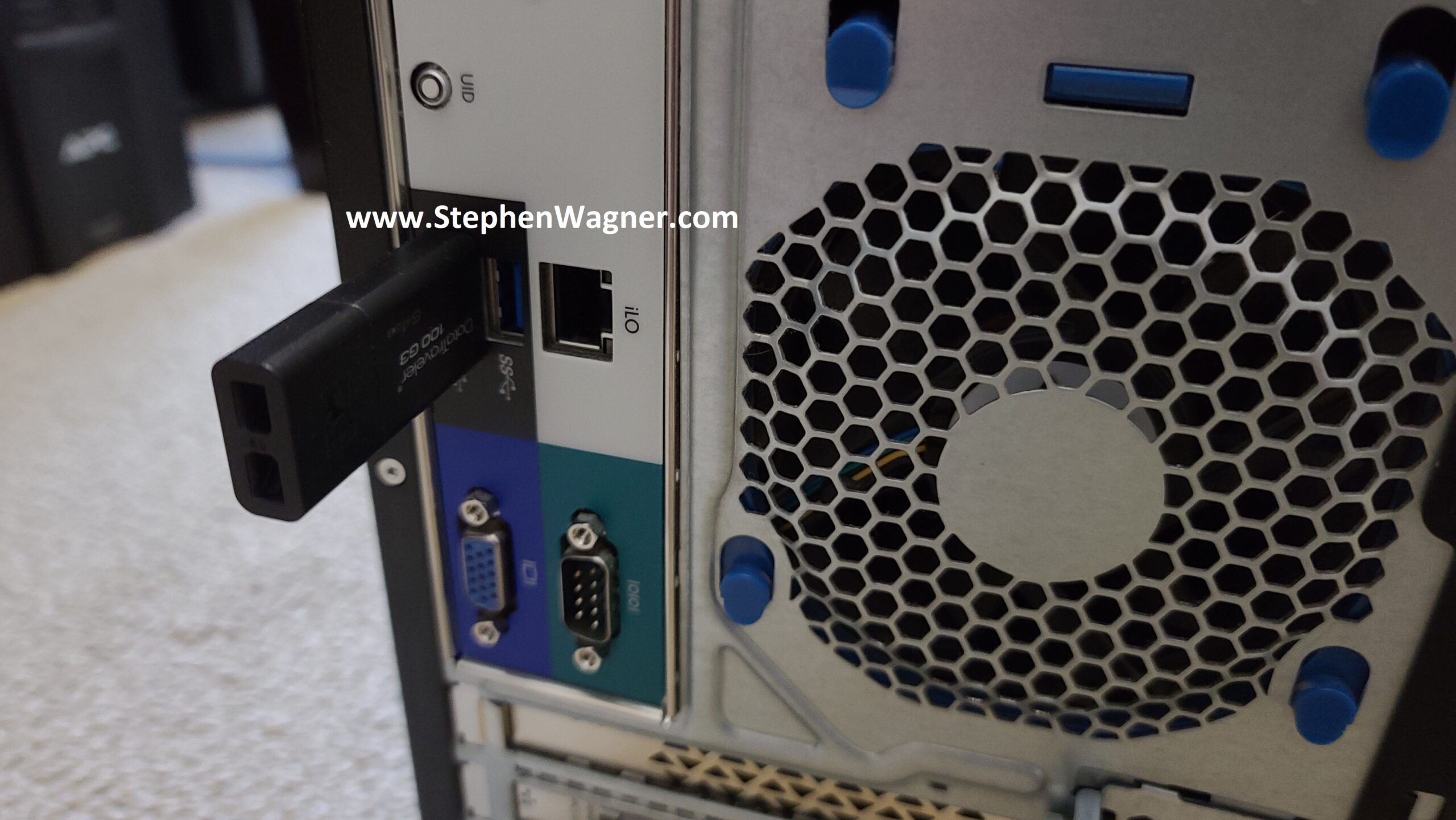
For the initial Proof-Of-Concept for version 2, I decided to be quick and dirty and install it to a USB stick. I also waited until I installed TrueNAS on to the USB stick and completed basic configuration before installing the Quad NVMe PCIe card and 10Gb NIC. I’m using a USB 3.0 port on the back of the server for speed, as I can’t verify if the port on the motherboard is USB 2 or USB 3.
TrueNAS USB Stick on HPE ML310e Gen8 v2
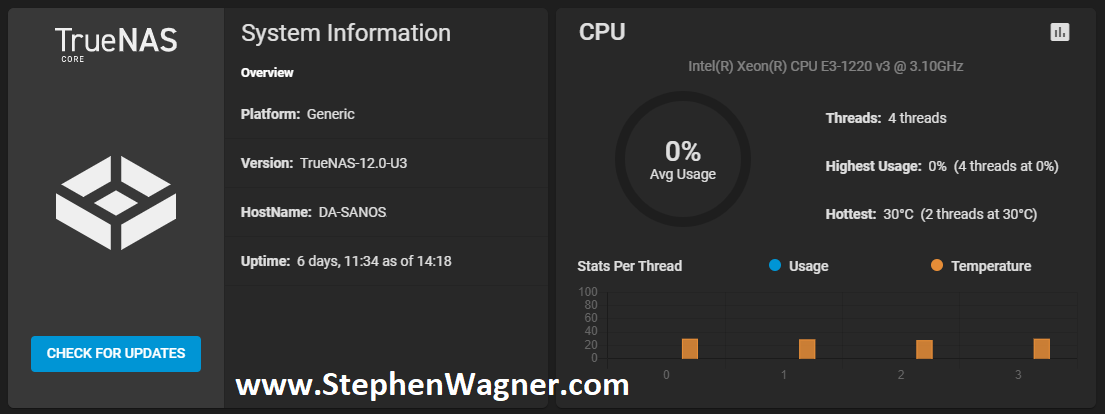
TrueNAS installation worked without any problems whatsoever on the ML310e. I configured the basic IP, time, accounts, and other generic settings. I then proceeded to install the PCIe cards (storage and networking).
TrueNAS Installed on NVMe Storage Server
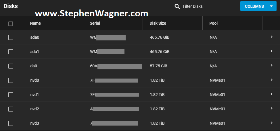
All NVMe drives were recognized, along with the 2 HDDs I had in the front Hot-swap bays (sitting on an HP B120i Controller configured in HBA mode).
TrueNAS NVMe Disks
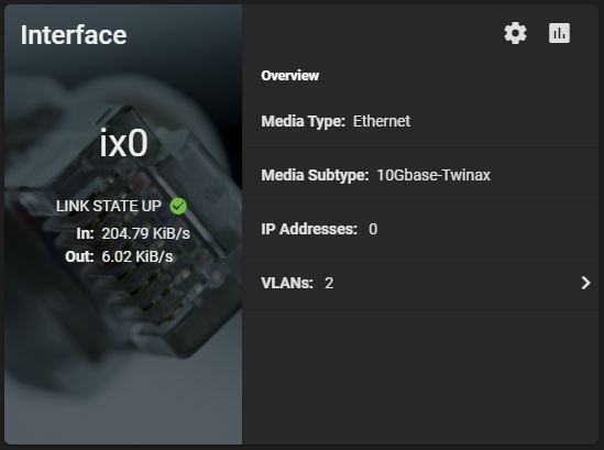
The 560SFP+ NIC also was detected without any issues and available to configure.
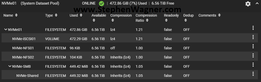
I created a striped pool (no redundancy) of all 4 x 2TB NVMe drives. This gave us around 8TB of usable high speed NVMe storage. I also created some datasets and a zVOL for iSCSI.
NVMe TrueNAS Storage Pool with Datasets and zVol
I chose to go with the defaults for compression to start with. I will be testing throughput and achievable speeds in the future. You should always test this in every and all custom environments as the results will always vary.
Network Configuration
Initial configuration was done via the 1Gb NIC connection to my main LAN network. I had to change this as the 10Gb NIC will be directly connected to the network backbone and needs to access the LAN and Storage VLANs.
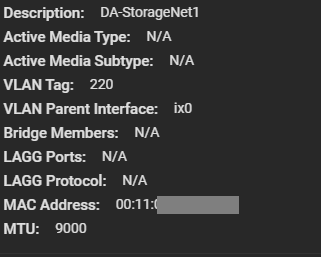
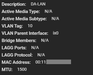
I went ahead and configured a VLAN Interface on VLAN 220 for the Storage network. Connections for iSCSI and NFS will be made on this network as all my ESXi servers have vmknics configured on this VLAN for storage. I also made sure to configure an MTU of 9000 for jumbo frames (packets) to increase performance. Remember that all hosts must have the same MTU to communicate.
10Gb NIC on Storage VLAN
Next up, I had to create another VLAN interface for the LAN network. This would be used for management, as well as to provide Windows File Share (SMB/Samba) access to the workstations on the network. We leave the MTU on this adapter as 1500 since that’s what my LAN network is using.
10Gb NIC on LAN VLAN
As a note, I had to delete the configuration for the existing management settings (don’t worry, it doesn’t take effect until you hit test) and configure the VLAN interface for my LANs VLAN and IP. I tested the settings, confirmed it was good, and it was all setup.
At this point, only the 10Gb NIC is now being used so I went ahead and disconnected the 1Gb network cable.
Sharing Setup and Configuration
It’s now time to configure the sharing protocols that will be used. As mentioned before, I plan on deploying iSCSI, NFS, and Windows File Shares (SMB/Samba).
iSCSI and NFS Configuration
Normally, for a VMware ESXi virtualization environment, I would always usually prefer iSCSI based storage, however I also wanted to configure NFS to test throughput of both with NVMe flash storage.
Earlier, I created the datasets for all my my NFS exports and a zVOL volume for iSCSI.
Note, that in order to take advantage of the VMware VAAI storage directives (enhancements), you must use a zVOL to present an iSCSI target to an ESXi host.
For NFS, you can simply create a dataset and then export it.
For iSCSI, you need to create a zVol and then configure the iSCSI Target settings and make it available.
SMB (Windows File Shares)
I needed to create a Windows File Share for file based storage from Windows computers. I plan on using the Windows File Share for high-speed storage of files for video editing.
Using the dataset I created earlier, I configured a Windows Share, user accounts, and tested accessing it. Works perfect!
Connecting the host
Connecting the ESXi hosts to the iSCSI targets and the NFS exports is done in the exact same way that you would with any other storage system, so I won’t be including details on that in this post.
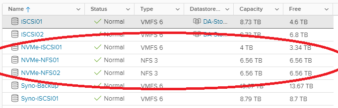
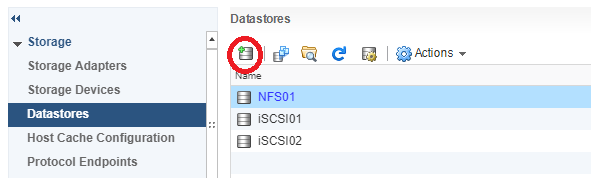
We can clearly see the iSCSI target and NFS exports on the ESXi host.
TrueNAS NVMe iSCSI Target on VMware ESXi Host
NVMe iSCSI and NFS ESXi Datastores
To access Windows File Shares, we log on and map the network share like you would normally with any file server.
Testing
For testing, I moved (using Storage vMotion) my main VDI desktop to the new NVMe based iSCSI Target LUN on the NVMe Storage Server. After testing iSCSI, I then used Storage vMotion again to move it to the NFS datastore. Please see below for the NVMe storage server speed test results.
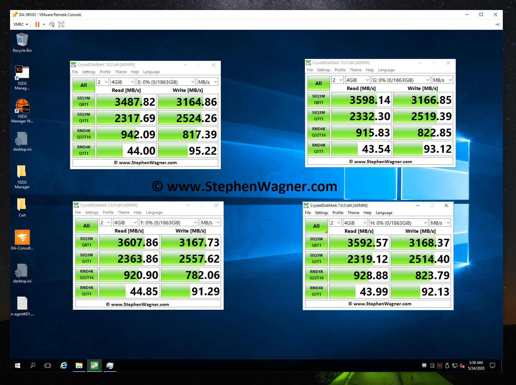
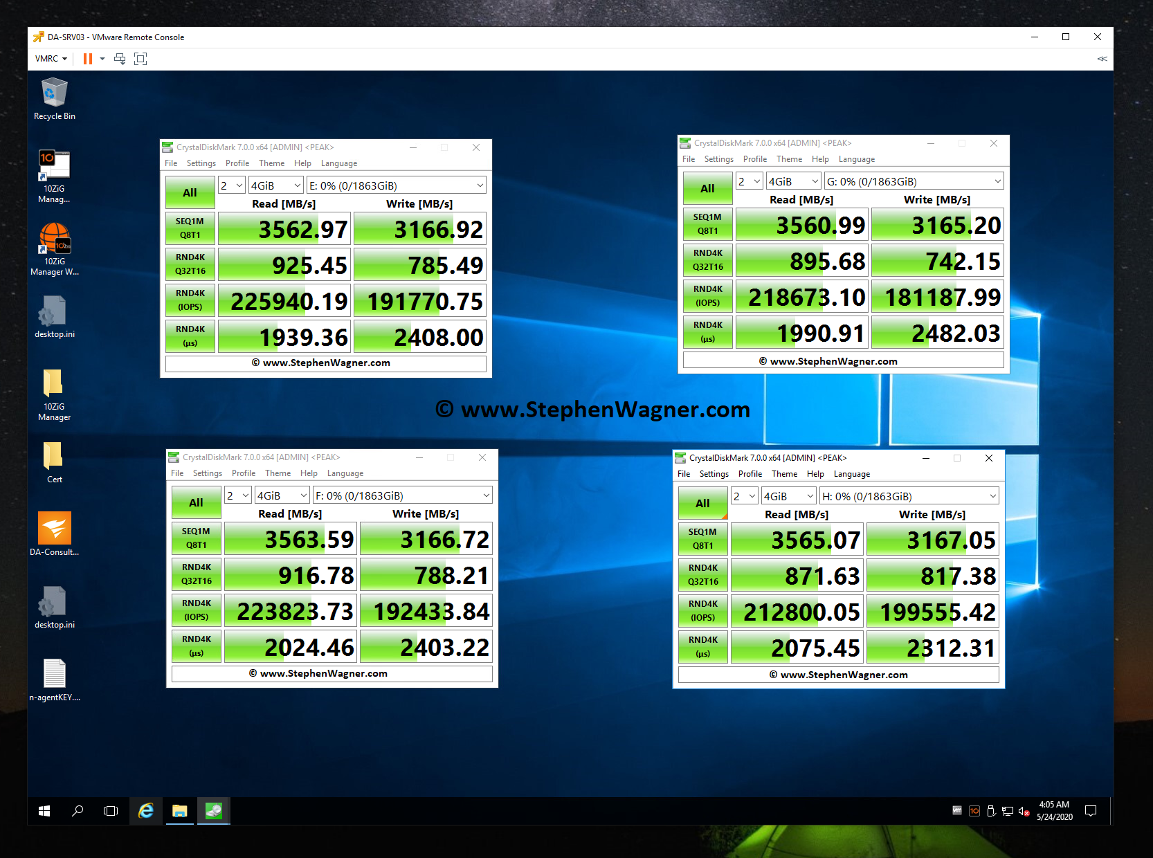
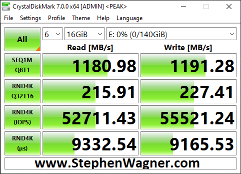
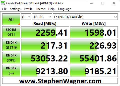
CrystalDiskMark testing an IOCREST IO-PEX40152 and Sabrent Rocket 4 NVME SSD
CrystalDiskMark testing IOPS on an IOCREST IO-PEX40152 and Sabrent Rocket 4 NVME SSD
Note, that when I performed these tests, my CPU was maxed out and limiting the actual throughput. Even then, these are some fairly impressive speeds. Also, these tests were directly testing each NVMe drive individually.
Moving on to the NVMe Storage Server, I decided to test iSCSI NVMe throughput and NFS NVMe throughput.
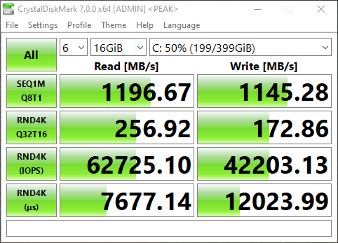
I opened up CrystalDiskMark and started a generic test, running a 16GB test file a total of 6 times on my VDI VM sitting on the iSCSI NVMe LUN.
NVMe Storage Server iSCSI Benchmark with CrystalDiskMark
You can see some impressive speeds maxing out the 10Gb NIC with crazy performance of the NVME storage:
1196MB/sec READ
1145.28MB/sec WRITE (Maxing out the 10GB NIC)
62,725.10 IOPS READ
42,203.13 IOPS WRITE
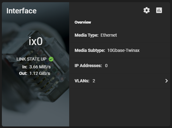
Additionally, here’s a screenshot of the ix0 NIC on the TrueNAS system during the speed test benchmark: 1.12 GiB/s.
TrueNAS NVME Maxing out 10Gig NIC
And remember this is with compression. I’m really excited to see how I can further tweak and optimize this, and also what increases will come with configuring iSCSI MPIO. I’m also going to try to increase the IOPS to get them closer to what each individual NVMe drive can do.
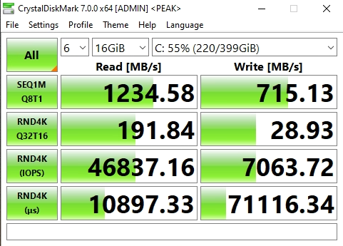
Now on to NFS, the results were horrible when moving the VM to the NFS Export.
NVMe Storage Server NFS Benchmark with CrystalDiskMark
You can see that the read speed was impressive, but the write speed was not. This is partly due to how writes are handled with NFS exports.
Clearly iSCSI is the best performing method for ESXi host connectivity to a TrueNAS based NVMe Storage Server. This works perfect because we’ll get the VAAI features (like being able to reclaim space).
iSCSI MPIO Speed Test
This is more of an update… I was finally able to connect, configure, and utilize the 2nd 10Gbe port on the 560SFP+ NIC. In my setup, both hosts and the TrueNAS storage server all have 2 connections to the switch, with 2 VLANs and 2 subnets dedicated to storage. Check out the before/after speed tests with enabling iSCSI MPIO.
TrueNAS NVME iSCSI MPIO BeforeTrueNAS NVME iSCSI MPIO AfterBefore and After enabling iSCSI MPIO on TrueNAS with NVME Storage
As you can see I was able to essentially double my read speeds (again maxing out the networking layer), however you’ll notice that the write speeds maxed out at 1598MB/sec. I believe we’ve reached a limitation of the CPU, PCIe bus, or something else inside of the server. Note, that this is not a limitation of the Sabrent Rocket 4 NVME drives, or the IOCREST NVME PCIe card.
Moving Forward
I’ve had this configuration running for around a week now with absolutely no issues, no crashes, and it’s been very stable.
Using a VDI VM on NVMe backed storage is lightning fast and I love the experience.
I plan on running like this for a little while to continue to test the stability of the environment before making more changes and expanding the configuration and usage.
Future Plans (and Configuration)
Drive Bays
I plan to populate the 4 hot-swappable drive bays with HPE 4TB MDL drives. Configured with RaidZ1, this should give me around 12TB usable storage. I can use this for file storage, backups, replication, and more.
NVMe Replication
This design was focused on creating non-redundant extremely fast storage. Because I’m limited to a total of 4 NVMe disks in this design, I chose not to use RaidZ and striped the data. If one NVMe drive is lost, all data is lost.
I don’t plan on storing anything important, and at this point the storage is only being used for VDI VMs (which are backed up), and Video editing.
If I can populate the front drive bays, I can replicate the NVMe storage to the traditional HDD storage on a frequent basis to protect against failure to some level or degree.
Version 3 of the NVMe Storage Server
More NVMe and Bigger NVMe – I want more storage! I want to test different levels of RaidZ, and connect to the backbone at even faster speeds.
NVME Drives with PLP (Power Loss Prevention) for data security and protection.
Dual Power Supply
Let me know your thoughts and ideas on this setup!
I’ve noticed in a few situations where an ESXi host is marked as “unresponsive” or “disconnected” inside of vCenter due to issues occurring on that host (or connected hardware). This recently happened again with a customer and is why I’m writing this article at this very moment.
In these situations, usually all normal means of managing, connecting, or troubleshooting the host are unavailable. Usually in cases like this ESXi administrators would simply reset the host.
However, I’ve found hosts can often be rescued without requiring an ungraceful restart or reset.
Observations
In these situations, it can be observed that:
The ESXi host is in a unresponsive to disconnected state to vCenter Server.
Connecting to the ESXi host directly does not work as it either doesn’t acknowledge HTTPS requests, or comes up with an error.
Accessing the console of the ESXi host isn’t possible as it appears frozen.
While the ESXi host is unresponsive, the virtual machines are still online and available on the network.
Troubleshooting
In the few situations I’ve noticed this occurring, troubleshooting is possible but requires patience. Consider the following:
When trying to access the ESXi console, give it time after hitting enter or selecting a value. If there’s issues on the host such as commands pending, tasks pending, or memory issues, the console may actually respond if you give it 30 seconds to 5 minutes after selecting an item.
With the above in mind, attempt to enable console access (preferably console and not SSH). The logins may take some time (30 seconds to 5 minutes after typing in the password), but you might be able to gain troubleshooting access.
Check the SAN, NAS, and any shared storage… In one instance, there were issues with a SAN and datastore that froze 2 VMs. The Queued commands to the SAN caused the ESXi host to become unresponsive.
There may be memory issues with the ESXi instance. The VMs are fine, however an agent, driver, or piece of software may be causing the hypervisor layer to become unresponsive.
If there are storage issues, do what you can. In one of the cases above, we had to access the ESXi console, issue a “kill -9” to the VM, and then restart the SAN. We later found out there was issues with the SAN and corrupted virtual machines. The moment the SAN was restarted, the ESXi host became responsive, connected to the vCenter server and could be managed.
In another instance, on an older version of ESXi there was an HPE agentless management driver/service that was consuming the ESXi hosts memory continuously causing the memory to overflow, the host to fill the swap and become unresponsive. Eventually after gracefully shutting down the VMs, I was able to access the console, kill the service, and the host become responsive.
We’ve all been in the situation where we need to install a driver, vib file, or check “esxtop”. Many advanced administration tasks on ESXi need to be performed via shell access, and to do this you either need a console on the physical ESXi host, an SSH session, or use the Remote vCLI.
In this blog post, I’m going to be providing a quick “How to” enable SSH on an ESXi host in your VMware Infrastructure using the vCenter flash-based web administration interface. This will allow you to perform the tasks above, as well as use the “esxcli” command which is frequently needed.
This method should work on all vCenter versions up to 6.7, and ESXi versions up to 6.7.
How to Enable SSH on an ESXi Host Server
Log on to your vCenter server.
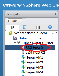
On the left hand “Navigator” pane, select the ESXi host.
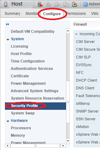
On the right hand pane, select the “Configure” tab, then “Security Profile” under “System.
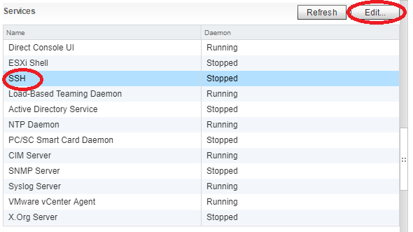
Scroll down and look for “Services” further to the right and select “Edit”.
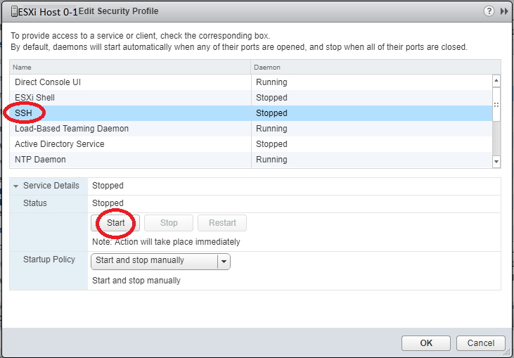
In the “Edit Security Profile” window, select and highlight “SSH” and then click “Start”.
Click “Ok”.
This method can also be used to stop, restart, and change the startup policy to enable or disable SSH starting on boot.
Congratulations, you can now SSH in to your ESXi host!
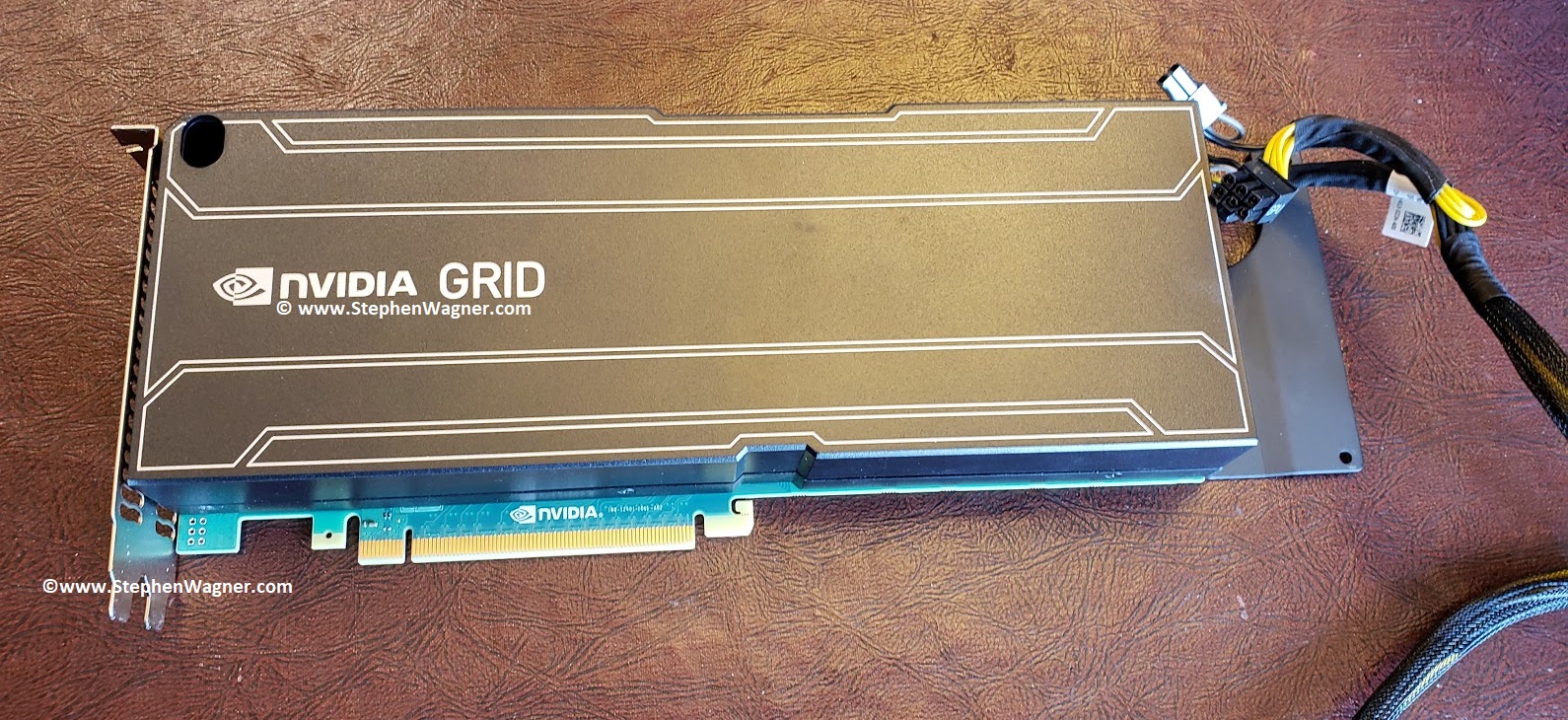
I can’t tell you how excited I am that after many years, I’ve finally gotten my hands on and purchased an Nvidia Quadro K1 GPU. This card will be used in my homelab to learn, and demo Nvidia GRID accelerated graphics on VMware Horizon View. In this post I’ll outline the details, installation, configuration, and thoughts. And of course I’ll have plenty of pictures below!
The focus will be to use this card both with vGPU, as well as 3D accelerated vSGA inside in an HPE server running ESXi 6.5 and VMware Horizon View 7.8.
Please Note: Some, most, or all of what I’m doing is not officially supported by Nvidia, HPE, and/or VMware. I am simply doing this to learn and demo, and there was a real possibility that it may not have worked since I’m not following the vendor HCL (Hardware Compatibility lists). If you attempt to do this, or something similar, you do so at your own risk.
For some time I’ve been trying to source either an Nvidia GRID K1/K2 or an AMD FirePro S7150 to get started with a simple homelab/demo environment. One of the reasons for the time it took was I didn’t want to spend too much on it, especially with the chances it may not even work.
Essentially, I have 3 Servers:
HPE DL360p Gen8 (Dual Proc, 128GB RAM)
HPE DL360p Gen8 (Dual Proc, 128GB RAM)
HPE ML310e Gen8 v2 (Single Proc, 32GB RAM)
For the DL360p servers, while the servers are beefy enough, have enough power (dual redundant power supplies), and resources, unfortunately the PCIe slots are half-height. In order for me to use a dual-height card, I’d need to rig something up to have an eGPU (external GPU) outside of the server.
As for the ML310e, it’s an entry level tower server. While it does support dual-height (dual slot) PCIe cards, it only has a single 350W power supply, misses some fancy server technologies (I’ve had issues with VT-d, etc), and only a single processor. I should be able to install the card, however I’m worried about powering it (it has no 6pin PCIe power connector), and having ESXi be able to use it.
Finally, I was worried about cooling. The GRID K1 and GRID K2 are typically passively cooled and meant to be installed in to rack servers with fans running at jet engine speeds. If I used the DL360p with an external setup, this would cause issues. If I used the ML310e internally, I had significant doubts that cooling would be enough. The ML310e did have the plastic air baffles, but only had one fan for the expansion cards area, and of course not all the air would pass through the GRID K1 card.
The Purchase
Because of a limited budget, and the possibility I may not even be able to get it working, I didn’t want to spend too much. I found an eBay user local in my city who had a couple Grid K1 and Grid K2 cards, as well as a bunch of other cool stuff.
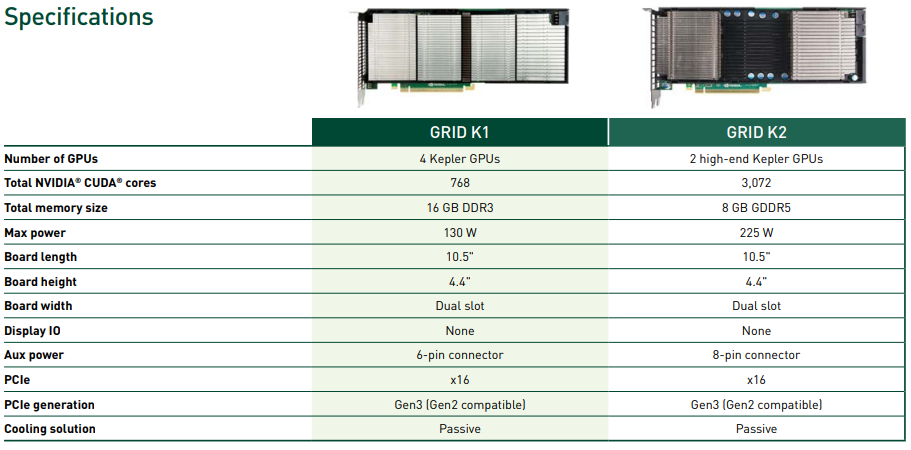
We spoke and he decided to give me a wicked deal on the Grid K1 card. I thought this was a fantastic idea as the power requirements were significantly less (more likely to work on the ML310e) on the K1 card at 130 W max power, versus the K2 card at 225 W max power.
We set a time and a place to meet. Preemptively I ran out to a local supply store to purchase an LP4 power adapter splitter, as well as a LP4 to 6pin PCIe power adapter. There were no available power connectors inside of the ML310e server so this was needed. I still thought the chances of this working were slim…
I also decided to go ahead and download the Nvidia GRID Software Package. This includes the release notes, user guide, ESXi vib driver (includes vSGA, vGPU), as well as guest drivers for vGPU and pass through. The package also includes the GRID vGPU Manager. The driver I used was from: https://www.nvidia.com/Download/driverResults.aspx/144909/en-us
To install, I copied over the vib file “NVIDIA-vGPU-kepler-VMware_ESXi_6.5_Host_Driver_367.130-1OEM.650.0.0.4598673.vib” to a datastore, enabled SSH, and then ran the following command to install:
The command completed successfully and I shut down the host. Now I waited to meet.
We finally met and the transaction went smooth in a parking lot (people were staring at us as I handed him cash, and he handed me a big brick of something folded inside of grey static wrap). The card looked like it was in beautiful shape, and we had a good but brief chat. I’ll definitely be purchasing some more hardware from him.
Hardware Installation
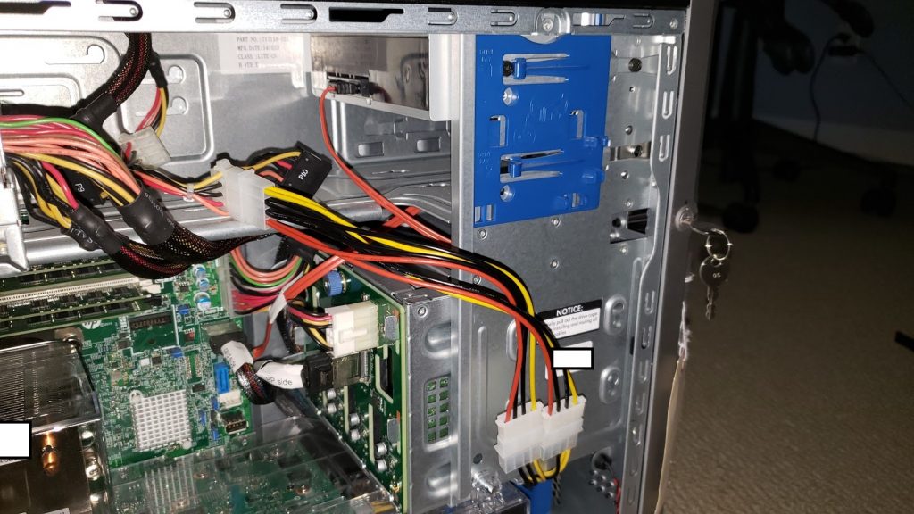
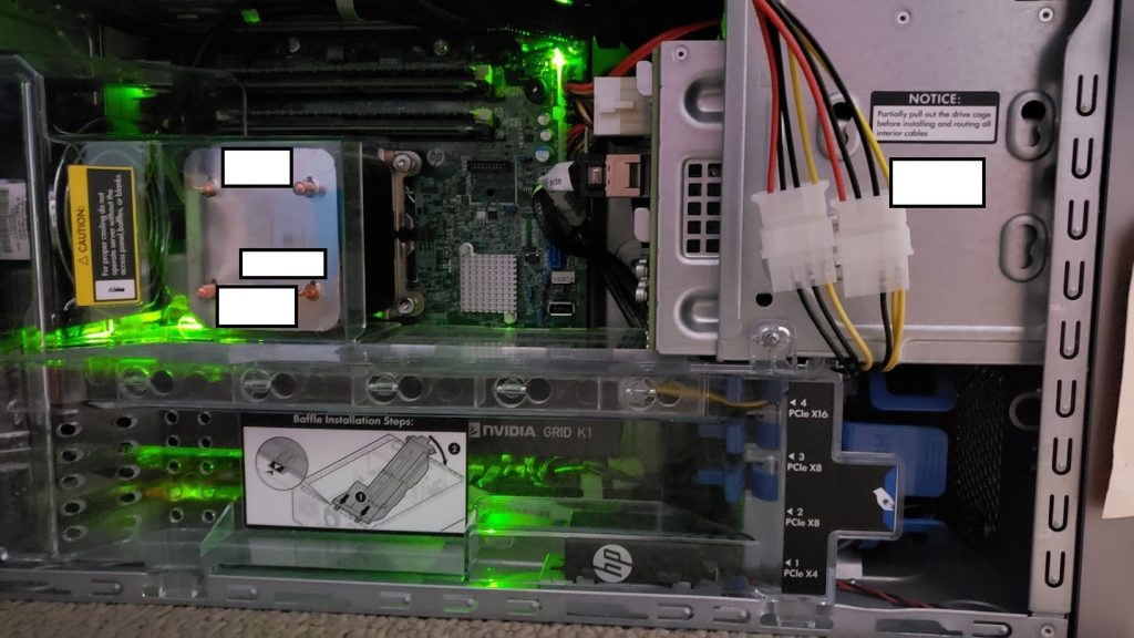
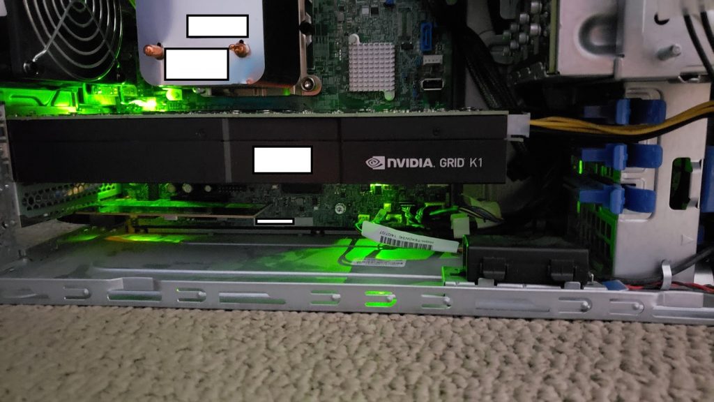
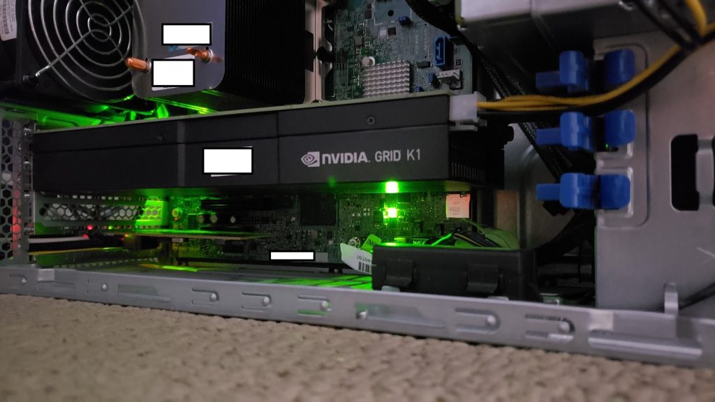
Installing the card in the ML310e was difficult and took some time with care. First I had to remove the plastic air baffle. Then I had issues getting it inside of the case as the back bracket was 1cm too long to be able to put the card in. I had to finesse and slide in on and angle but finally got it installed. The back bracket (front side of case) on the other side slid in to the blue plastic case bracket. This was nice as the ML310e was designed for extremely long PCIe expansion cards and has a bracket on the front side of the case to help support and hold the card up as well.
For power I disconnected the DVD-ROM (who uses those anyways, right?), and connected the LP5 splitter and the LP5 to 6pin power adapter. I finally hooked it up to the card.
I laid the cables out nicely and then re-installed the air baffle. Everything was snug and tight.
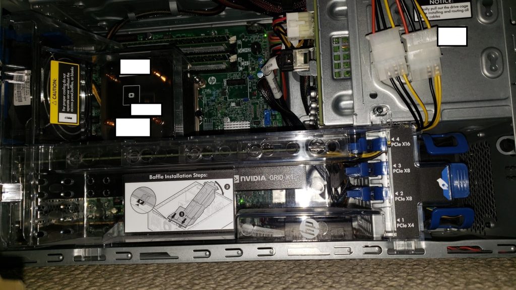
Please see below for pictures of the Nvidia GRID K1 installed in the ML310e Gen8 V2.
ML310e with GRID K1 Side Shot
ML310e with GRID K1 Side Shot (with Flash)
ML310e w/ Air Baffle and cabling
ML310e LP4 Splitter for GRID K1
Nvidia GRID K1 in ML310e w/ Air Baffle
Nvidia GRID K1 Installed and Running
Nvidia GRID K1 in ML310e w/o Air Baffle
Host Configuration
Powering on the server was a tense moment for me. A few things could have happened:
Server won’t power on
Server would power on but hang & report health alert
Nvidia GRID card could overheat
Nvidia GRID card could overheat and become damaged
Nvidia GRID card could overheat and catch fire
Server would boot but not recognize the card
Server would boot, recognize the card, but not work
Server would boot, recognize the card, and work
With great suspense, the server powered on as per normal. No errors or health alerts were presented.
I logged in to iLo on the server, and watched the server perform a BIOS POST, and start it’s boot to ESXi. Everything was looking well and normal.
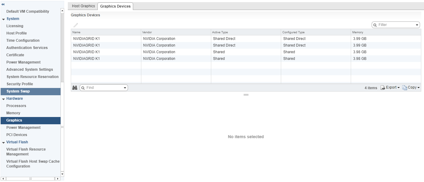
After ESXi booted, and the server came online in vCenter. I went to the server and confirmed the GRID K1 was detected. I went ahead and configured 2 GPUs for vGPU, and 2 GPUs for 3D vSGA.
ESXi Host Graphics Devices Settings
VM Configuration
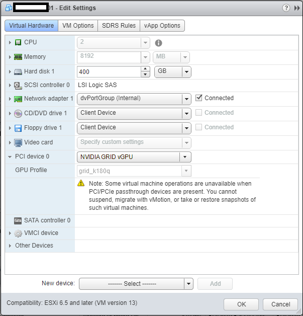
I restarted the X.org service (required when changing the options above), and proceeded to add a vGPU to a virtual machine I already had configured and was using for VDI. You do this by adding a “Shared PCI Device”, selecting “NVIDIA GRID vGPU”, and I chose to use the highest profile available on the K1 card called “grid_k180q”.
VM Settings to add NVIDIA GRID vGPU
After adding and selecting ok, you should see a warning telling you that must allocate and reserve all resources for the virtual machine, click “ok” and continue.
Power On and Testing
I went ahead and powered on the VM. I used the vSphere VM console to install the Nvidia GRID driver package (included in the driver ZIP file downloaded earlier) on the guest. I then restarted the guest.
After restarting, I logged in via Horizon, and could instantly tell it was working. Next step was to disable the VMware vSGA Display Adapter in the “Device Manager” and restart the host again.
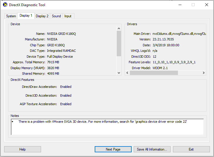
Upon restarting again, to see if I had full 3D acceleration, I opened DirectX diagnostics by clicking on “Start” -> “Run” -> “dxdiag”.
dxdiag on GRID K1 using k180q profile
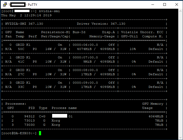
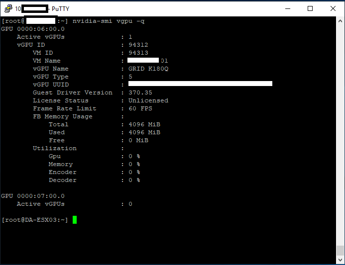
It worked! Now it was time to check the temperature of the card to make sure nothing was overheating. I enabled SSH on the ESXi host, logged in, and ran the “nvidia-smi” command.
“nvidia-smi” command on ESXi Host
According to this, the different GPUs ranged from 33C to 50C which was PERFECT! Further testing under stress, and I haven’t gotten a core to go above 56. The ML310e still has an option in the BIOS to increase fan speed, which I may test in the future if the temps get higher.
With “nvidia-smi” you can see the 4 GPUs, power usage, temperatures, memory usage, GPU utilization, and processes. This is the main GPU manager for the card. There are some other flags you can use for relevant information.
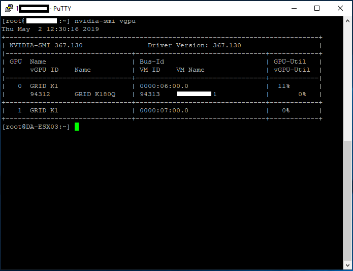
“nvidia-smi vgpu” for vGPU Information“nvidia-smi vgpu -q” to Query more vGPU Information
Final Thoughts
Overall I’m very impressed, and it’s working great. While I haven’t tested any games, it’s working perfect for videos, music, YouTube, and multi-monitor support on my 10ZiG 5948qv. I’m using 2 displays with both running at 1920×1080 for resolution.
I’m looking forward to doing some tests with this VM while continuing to use vGPU. I will also be doing some testing utilizing 3D Accelerated vSGA.
The two coolest parts of this project are:
3D Acceleration and Hardware h.264 Encoding on VMware Horizon
Getting a GRID K1 working on an HPE ML310e Gen8 v2
Highly recommend getting a setup like this for your own homelab!
Uses and Projects
Well, I’m writing this “Uses and Projects” section after I wrote the original article (it’s now March 8th, 2020). I have to say I couldn’t be impressed more with this setup, using it as my daily driver.
Since I’ve set this up, I’ve used it remotely while on airplanes, working while travelling, even for video editing.
Some of the projects (and posts) I’ve done, can be found here:
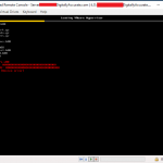
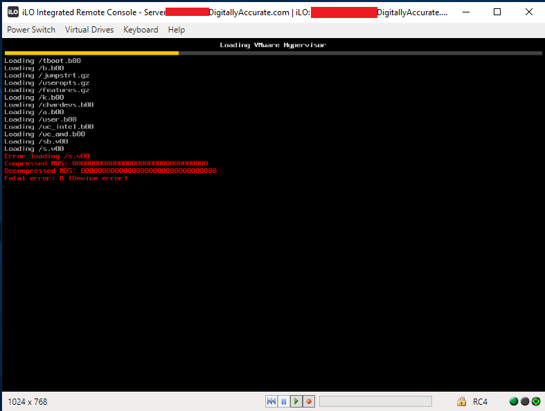
Unable to boot ESXi from USB or SD Card on HPE Proliant Server
After installing HPE iLO Amplifier on your network and updating iLO 4 firmware to 2.60 or 2.61, you may notice that your HPE Proliant Servers may fail to boot ESXi from a USB drive or SD-Card.
This was occuring on 2 ESXi Hosts. Both were HPE Proliant DL360p Gen8 Servers. One server was using an internal USB drive for ESXi, while the other was using an HPE branded SD Card.
The issue started occuring on both hosts after a planned InfoSight implementation. Both hosts iLO controllers firmware were upgraded to 2.61, iLO Amplifier was deployed (and the servers added), and the amplifier was connected to an HPE InfoSight account.
Update – May 24th 2019: As an HPE partner, I have been working with HPE, the product manager, and development team on this issue. HPE has provided me with a fix to test that I have been able to verify fully resolves this issue! Stay tuned for more information!
Update – June 5th 2019: Great news! As Bob Perugini (WW Product Manager at HPE) put it: “HPE is happy to announce that this issue has been fixed in latest version of iLO Amplifier Pack, v1.40. To download iLO Amplifier Pack v1.40, go to http://www.hpe.com/servers/iloamplifierpack and click “download”.” Scroll to the bottom of the post for more information!
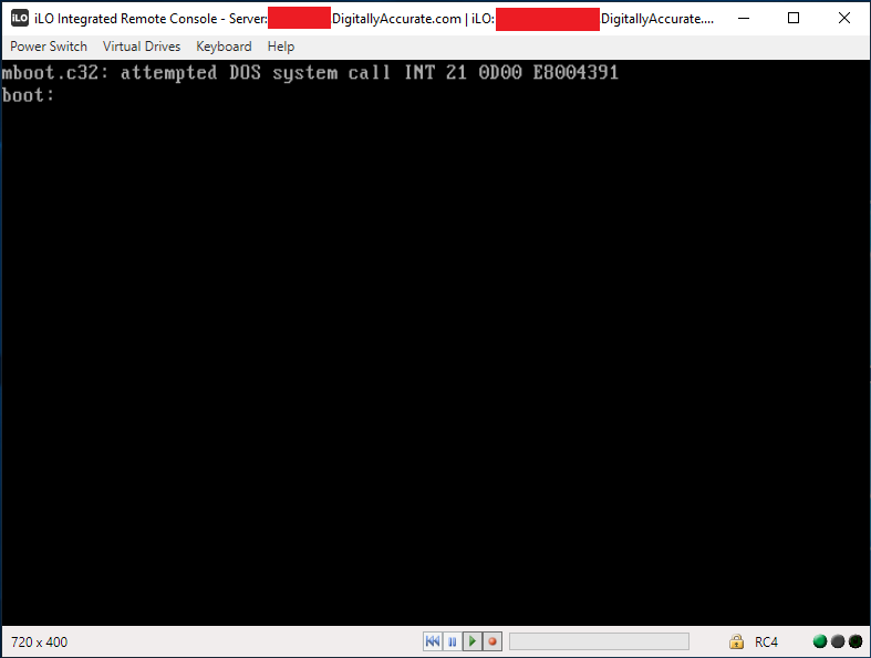
mboot.c32: attempted DOS system call INT 21 0d00 E8004391
 boot:
Symptoms
This issue may occur intermittently, on the majority of boots, or on all boots. Re-installing ESXi on the media, as well as replacing the USB/SD Card has no effect. Installation will be successful, however you the issue is still experiences on boot.
HPE technical support was unable to determine the root of the issue. We found the source of the issue and reported it to HPE technical support and are waiting for an update.
The Issue and Fix
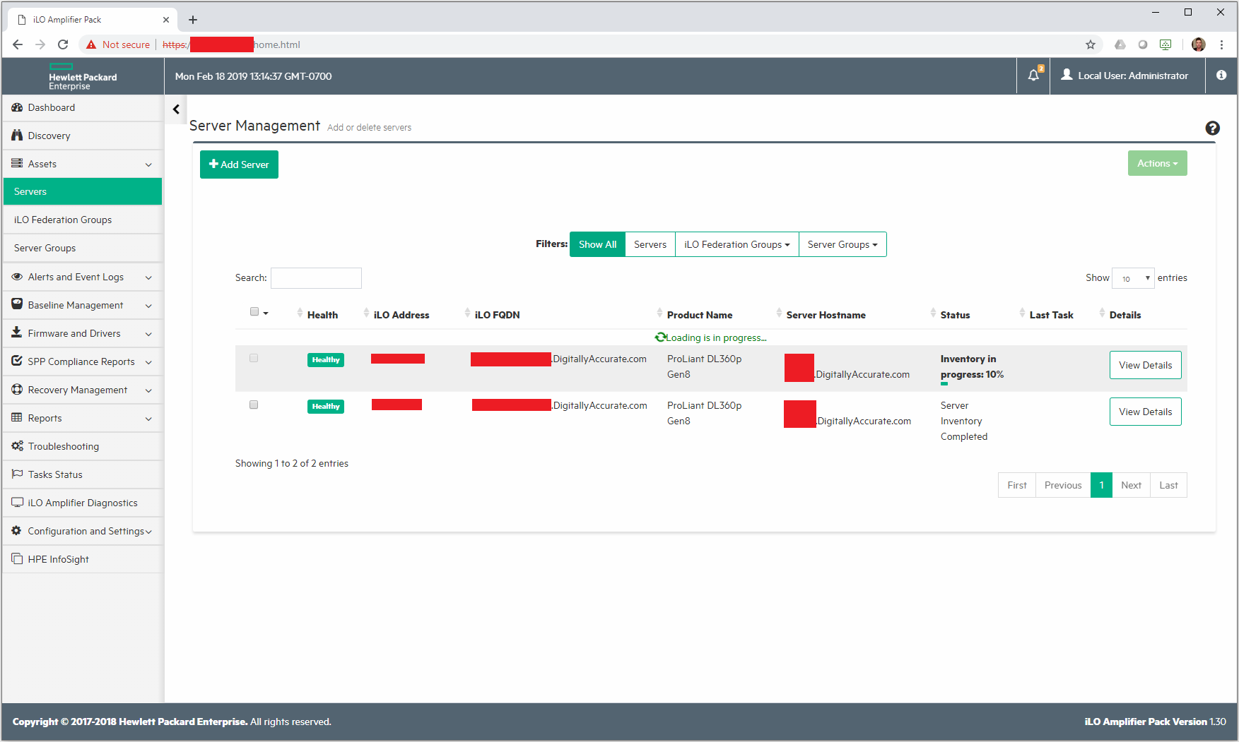
This issue occurs because the HPE iLO Amplifier is running continuous server inventory scans while the hosts are booting. When one inventory completes, it restarts another scan.
The following can be noted:
iLO Amplifier inventory percentage resets back to 0% and starts again numerous times during the server boot
Inventory scan completes, only to restart again numerous times during the server boot
Inventory scan resets back to 0% during numerous different phases of BIOS initialization and POST.
HPE iLO Amplifier Inventory
We noticed that once the HPE iLO Amplifier Virtual Machine was powered off, not only did the servers boot faster, but they also booted 100% succesfully each time. Powering on the iLO Amplifier would cause the ESXi hosts to fail to boot once again.
I’d also like to note that on the host using the SD-Card, the failed boot would actually completely lock up iLO, and would require physical intervention to disconnect and reconnect the power to the server. We were unable to restart the server once it froze (this did not happen to the host using the USB drive).
There are some settings on the HPE iLO amplifier to control performance and intervals of inventory scans, however we noticed that modifying these settings did not alter or stop the issue, and had no effect.
As a temporary workaround, make sure your iLO amplifier is powered off during any maintenance to avoid hosts freezing/failing to boot.
To fully resolve this issue, upgrade your iLO Amplifier to the latest version (1.40 as of the time of this update). The latest version can be downloaded at: http://www.hpe.com/servers/iloamplifierpack.
Update – April 10th 2019
I’ve attempted to try downgrading to the earliest supported iLo version 2.54, and the issue still occurs.
I also upgraded to the newest version 2.62 which presented some new issues.
On the first boot, the BIOS reported memory access issues on Processor 1 socket 1, then another error reporting memory access issues on Processor 1 socket 4.
I disconnected the power cables, reconnected, and restarted the server. This boot, the server didn’t even detect the bootable USB stick.
Again, after shutting down the iLo Amplifier, the server booted properly and the issue disappeared.
Update – May 24th 2019
As an HPE partner, I have been working with HPE, the product manager, and development team on this issue. HPE has provided me with a fix to test that I have been able to verify fully resolves this issue! Stay tuned for more information!
Update – June 5th 2019 – ITS FIXED!!!
Great news as the issue is now fixed! As Bob Perugini (WorldWide Product Manager at HPE) said it:
HPE is happy to announce that this issue has been fixed in latest version of iLO Amplifier Pack, v1.40.
Here’s what’s new in iLO Amplifier Pack v1.40: ─ Available as a VMware ESXi appliance and as a Hyper-V appliance (Hyper-V is new) ─ VMware tools have been added to the ESXi appliance ─ Ability to schedule the time of the daily transmission of Active Health System (AHS) data to InfoSight ─ Ability to opt-in and allow the IP address and hostname of the server to be transmitted to InfoSight and displayed ─ Test connectivity button to help verify iLO Amplifier Pack has successfully connected to InfoSight ─ Allow user authentication credentials for the proxy server when connecting to InfoSight ─ Added ability to specify IP address or hostname for the HPE RDA connection when connection to InfoSight ─ Ability to send updated AHS data “now” for an individual server ─ Ability to stage firmware and driver updates to the iLO Repository and then deploy the staged updates at a later date or time (HPE Gen10 servers only) ─ Allow the firmware and driver updates of servers whose iLO has been configured in CNSA (Commercial National Security Algorithm) mode (HPE Gen10 servers only)
On an ESXi host when performing a manual unmap on your storage datastore, you may notice a very large (hidden) file on the datastore root called “.asyncUnmapFile”. This file could be taking up terabytes of space, and you aren’t able to delete this file.
asyncUnmapFile
Typically the asyncUnmapFile is used by the UNMAP feature on ESXi hosts to deal with unmapping and unallocating storage blocks on the SAN. When you run a manual UNMAP, this file should be created and should appear to using “0” (no) space (even if it is). When an UNMAP completes, this file should disappear and be automatically removed by the function. If an UNMAP is interupted, this file will not be deleted, allowing you to restart the process and upon a full successful completion, it should then be deleted.
The Problem
Some time ago, I had an issue when performing a manual UNMAP, where the ESXi host became unresponsive (due to memory issues). The command appeared to be completed, however I believe it caused potential issues or corruption on the iSCSI datastore. In subsequent runs, the UNMAP appeared to be functioning and working, however I didn’t realize that the asyncUnmapFile had grown to around 1.5TB.
This was noticed during a SAN storage audit, where we saw that the virtual pool on the SAN was using up way more storage than it should be on the datastore.
When we identified the file was this large and causing issues, we attempted to perform 2 UNMAPs (different reclaim sizes) to see if it would be automatically cleared afterwards. It had no effect and the file was unchanged.
We also tried to modify the permissions on the file, however when trying to delete it, it would report that the file or folder was not found, or that it does not exist. This was concerning as we were worried about potential datastore corruption.
It was also noticed that in the hostd.log and vmkernel.log we saw some errors where the host believed that the blocks on the datastore had already been freed: “on volume labeled ‘iSCSIDatastore01’ already freed by another host: This may be a non-issue”
The Solution
Unfortunately with all the research we did, we couldn’t find a clear-cut solution. With worries that the datastore may be corrupted, we needed to do something.
A decision was ultimately made to Storage vMotion all the VMs (Virtual Machines) to another datastore on a separate storage pool, delete the now empty LUN, and recreate it from scratch. After this, we used Storage vMotion again to move the VMs back.
Instantly I noticed that the VMs on that datastore were running faster (it’s only been 12 hours, so I’ll be adding an update in a few days to confirm). We no longer have the file on any of our datastores.
If anyone has further insight in to this issue, please leave a comment!
So, what happens in a worst-case scenario where your backup system fails, you don’t have any VM snapshots, and the last thing standing in the way of complete data loss is your SAN storage systems LUN snapshots?
Well, first you fire whoever purchased and implemented the backup system, then secondly you need to start restoring the VM (or VMs) from your SAN LUN snapshots.
While I’ve never had to do this in the past (all the disaster recovery solutions I’ve designed and sold have been tested and function), I’ve always been curious what the process is and would be like. Today I decided to try it out and develop a procedure for restoring a VM from SAN Storage LUN snapshot.
For this test I pretended a VM was corrupt on my VMware vSphere cluster and then restored it to a previous state from a LUN snapshot on my HPE MSA 2040 (identical for the HPE MSA 2050, and MSA 2052) Dual Controller SAN.
To accomplish the restore, we’ll need to create a host mapping on the SAN for the LUN snapshot to a new LUN number available to the hosts. We then need to add and mount the VMFS volume (residing on the snapshot) to the host(s) while assigning it a new signature and then vMotion the VM from the snapshot’s VMFS to original datastore.
Important Notes (Read first):
When mounting a VMFS volume from a SAN snapshot, you MUST RE-SIGNATURE THE SNAPSHOT VMFS volume. Not doing so can cause problems.
The snapshot cannot be mapped as read only, VMFS volumes must be marked as writable in order to be mounted on ESXi hosts.
You must follow the proper procedure to gracefully dismount and detach the VMFS volume and storage device before removing the snapshot’s host mapping on the SAN.
We use Storage vMotion to perform a high-speed move and recovery of the VM. If you’re not licensed for Storage vMotion, you can use the datastore file browser and copy/move from the snapshot VMFS volume to live production VMFS volume, however this may be slower.
During this entire process you do not touch, modify, or change any settings on your existing active production LUNs (or LUN numbers).
Restoring a VM from a SAN LUN snapshot will restore a crash consistent copy of the VM. The VM when recovered will believe a system crash occurred and power was lost. This is NOT a graceful application consistent backup and restore.
Please read your SAN documentation for the procedure to access SAN snapshots, and create host mappings. With the MSA 2040 I can do this live during production, however your SAN may be different and your hosts may need to be powered off and disconnected while SAN configuration changes are made.
Pro tip: You can also power on and initialize the VM from the snapshot before initiating the storage vMotion. This will allow you to get production services back online while you’re moving the VM from the snapshot to production VMFS volumes.
I’m not responsible if you damage, corrupt, or cause any damage or issues to your environment if you follow these procedures.
We are assuming that you have already either deleted the damaged VM, or removed it from your inventory and renamed the VMs folder on the live VMFS datastore to change the name (example, renaming the folder from “SRV01” to “SRV01.bad”. If you renamed the damaged VM, make sure you have enough space for the new restored VM as well.
Procedure:
Mount the VMFS volume on the LUN snapshot to the ESXi host(s)
Identify the VM you want to recover, write it down.
Identify the datastore that the VM resides on, write it down.
Identify the SAN and identify the LUN number that the VMFS datastore resides on, write it down.
Identify the LUN Snapshot unique name/id/number and write it down, confirm the timestamp to make sure it will contain a valid recovery point.
Log on to the SAN and create a host mapping to present the snapshot (you recorded above) to the hosts using a new and unused LUN number.
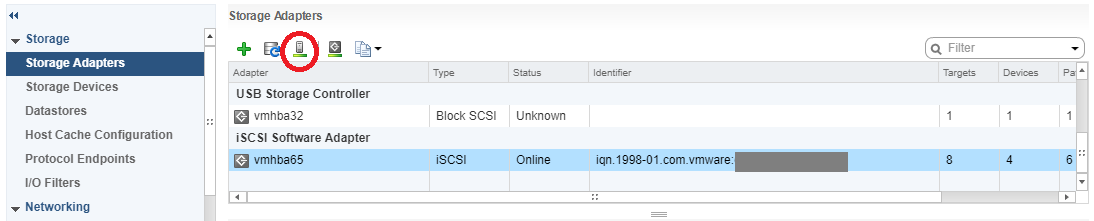
Log on to your ESXi host and navigate to configuration, then storage adapters.
Select the iSCSI initator and click the “Rescan Storage Adapters” button to rescan all iSCSI LUNs.
VMware ESXi Host Rescan Storage Adapter
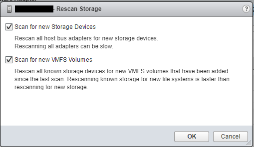
Ensure both check boxes are checked and hit “Ok”, wait for the scan to complete (as shown in the “Recent Tasks” window.
VMware ESXi Host Rescan Storage Adapter Window for VMFS Volume and Devices
Now navigate to the “Datastores” tab under configuration, and click on the “Create a new Datastore” button as shown below.
VMware ESXi Host Add Datastore Window
Continue with “VMFS” selected and select continue.
In the next window, you’ll see your existing datastores, as well as your new datastore (from the snapshot). You can leave the “Datastore name” as is since this value will be ignored. In this window you’re going to select the new VMFS datastore from the snapshot. Make sure you confirm this by looking at the LUN number, as well as the value under “SnapshotVolume”. It is critical that you select the snapshot in this window (it should be the new LUN number you added above).
Select next and continue.
On the next window “Mount Option”, you need to change the radio button to and select “Assign a new signature”. This is critical! This will assign a new signature to differentiate it from your existing real production datastore so that the ESXi hosts don’t confuse it.
Continue with the wizard and complete the mount process. At this point ESXi will resignture the VMFS volume and rename it to “snap-OriginalVolumeNameHere”.
You can now browse the VMFS datastore residing on the LUN snapshot and do anything you’d normally be able to do with a normal datastore.
Copy/Move/vMotion the VM from the snapshot VMFS volume to your production VMFS volume
Note: The next steps are only if you are licensed for storage vMotion. If you aren’t you’ll need to use the copy or move function in the file browsing area to copy or move the VMs to your live production VMFS datastores:
Now we’ll go to the vCenter/ESXi host storage area in the web client, and using the “Files” tab, we’ll browse the snapshots VMFS datastore that we just mounted.
Locate the folder for the VM(s) you want to recover, open the folder, right click on the vmx file for the VM and select “Register VM”. Repeat this for any of the VMs you want to recover from the snapshot. Complete the wizard for each VM you register and add it to a host.
Go back to you “Hosts and VMs” view, you’ll now see the VMs are added.
Select and right click on the VM you want to move from the snapshot datastore to your production live datastore, and select “Migrate”.
In the vMotion migrate wizard, select “Change Storage only”.
Continue to the wizard, and storage vMotion the VM from the snapshot VMFS to your production VMFS volume. Wait for the vMotion to complete.
After the storage vMotion is complete, boot the VM and confirm everything is functioning.
Gracefully unmount, detach, and remove the snapshot VMFS from the ESXi host, and then remove the host mapping from the SAN
On each of your ESXi hosts that have access to the SAN, go to the “Datastores” section under the ESXi hosts configuration, right click on the snapshot VMFS datastore, and select “Unmount”. You’ll need to repeat this on each ESXi host that may have automounted the snapshot’s VMFS volume.
On each of your ESXi hosts that have access to the SAN, go to the “Storage Devices” section under the ESXi hosts configuration and identify (by LUN number) the “disk” that is the snapshot LUN. Select and highlight the snapshot LUN disk, select “All Actions” and select “Detach”. Repeat this on each host.
Double check and confirm that the snapshot VMFS datastore (and disk object) have been unmounted and detached from each ESXi host.
You can now log in to your SAN and remove the host mapping for the snapshot-to-LUN. We will not longer present the snapshot LUN to any of the hosts.
Back to the ESXi hosts, navigate to “Storage Adapters”, select the “iSCSI Initiator Adapter”, and click the “Rescan Storage Adapters”. Repeat this for each ESXi host.
This website uses cookies to improve your experience. We'll assume you're ok with this, but you can opt-out if you wish.
Do you accept the use of cookies and accept our privacy policy? AcceptRejectCookie and Privacy Policy
Privacy & Cookies Policy
Privacy Overview
This website uses cookies to improve your experience while you navigate through the website. Out of these cookies, the cookies that are categorized as necessary are stored on your browser as they are essential for the working of basic functionalities of the website. We also use third-party cookies that help us analyze and understand how you use this website. These cookies will be stored in your browser only with your consent. You also have the option to opt-out of these cookies. But opting out of some of these cookies may have an effect on your browsing experience.