In some scenarios, you may encounter an issue where the Veeam WAN Accelerator service fails to start.
This will cause backup and backup copy jobs to fail that use the Veeam WAN Accelerator, which is how this issue is usually first diagnosed.
In this post I’ll explain the problem, what can cause it, and how to resolve the issue.
The Problem
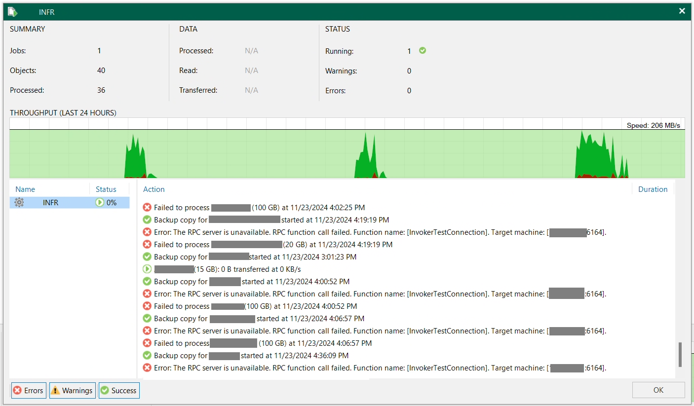
When this issue occurs, and when a Backup or Backup Copy job runs, it will usually first fail with the following error from the Veeam console:
Error: The RPC server is unavailable. RPC function call failed. Function name: [InvokerTestConnection]. Target machine: [IP.OF.WAN.ACC:6464].

Failed to process (VM Name).
See below for a screenshot of the example:
From the error above, the next step is usually to check the logs to find out what’s happening. Because this Backup Copy job uses the WAN accelerator, we’ll look at the log for the Veeam WAN Accelerator Service.
Svc.VeeamWANSvc.log
[23.11.2024 11:46:24.251] <  3440> srv      | RootFolder = V:\VeeamWAN
[23.11.2024 11:46:24.251] <  3440> srv      | SendFilesPath = V:\VeeamWAN\Send
[23.11.2024 11:46:24.251] <  3440> srv      | RecvFilesPath = V:\VeeamWAN\Recv
[23.11.2024 11:46:24.251] <  3440> srv      | EnablePerformanceMode = true
[23.11.2024 11:46:24.255] <  3440> srv      | ERR |Fatal error
[23.11.2024 11:46:24.255] <  3440> srv      | >>  |boost::filesystem::create_directories: The system cannot find the path specified: "V:\"
[23.11.2024 11:46:24.255] <  3440> srv      | >>  |Unable to apply settings. See log for details.
[23.11.2024 11:46:24.255] <  3440> srv      | >>  |An exception was thrown from thread [3440].
[23.11.2024 11:46:24.255] <  3440> srv      | Stopping service...
[23.11.2024 11:46:24.256] <  3440> srv      | Stopping retention thread...
[23.11.2024 11:46:24.257] <  4576>          | Thread started.  Role: 'Retention thread', thread id: 4576, parent id: 3440.
[23.11.2024 11:46:24.258] <  4576>          | Thread finished. Role: 'Retention thread'.
[23.11.2024 11:46:24.258] <  3440> srv      | Waiting for a client('XXX-Veeam-WAN:6165')
[23.11.2024 11:46:24.258] <  3440> srv      | Stopping server listening thread.
[23.11.2024 11:46:24.258] <  3440> srv      |   Stopping command handler threads.
[23.11.2024 11:46:24.258] <  3440> srv      |   Command handler threads have stopped.
[23.11.2024 11:46:24.258] <  4580>          | Thread started.  Role: 'Server thread', thread id: 4580, parent id: 3440.
In the Veeam WAN Service log file above, you’ll note a fatal error where the service is unable to find the paths configured, which caused the service to halt and stop.
In some configurations, iSCSI is used to access Veeam backup repository storage hosted on iSCSI targets. Furthermore, in some iSCSI configurations special vendor plugins are used to access the iSCSI storage, and configure items like MPIO (multipath input output), which can take additional time to initialize.
In this scenario, the Veeam WAN Accelerator Service was starting before the Windows iSCSI service, MPIO Service, and Nimble Windows Connection Manager plugin had time to initialize, resulting in the WAN accelerator failing because it couldn’t find the directories it was expecting.
The Solution
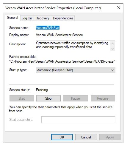
To resolve this issue, we want the Veeam WAN Accelerator Service to have a delayed start on the Windows Server operating system bootup sequence.
- Open Windows Services
- Select “Veeam WAN Accelerator Service”
- Change “Startup Type” to “Automatic (Delayed Start)”
- Click “Apply” to save, and then click “Start” to start the service.
As per the screenshot below:
The Veeam WAN Accelerator Service will now have a delayed start on system bootup, allowing the iSCSI initiator to establish and mount all iSCSI Target block devices, before starting the WAN service.