Mar 302020
 
Office 365 Logo

Once you deploy Remote Desktop Services (RDS) for employee remote access, your next step will be to install user applications as well as all your line of business applications.

One of the most widely used applications suite is Microsoft Office, particularly Microsoft Office 365.

In order to deploy Microsoft Office 365 in a Remote Desktop Services environment, a number of requirements must be met. There is also special instructions which must be followed to properly deploy it.

This information also applies when you want to install Office 365 / Microsoft 365 to a shared virtual machine or a golden image for VDI (for VDI you can read my full guide “Deploy, Install, and Configure Microsoft Office 365 in a VDI Environment“).

After reading and completing the steps in this blog post and deploying Office 365, you can head over to my guide on how to Configure Office 365 in a Remote Desktop Services Environment using GPOs to pre-configure Microsoft Office and it’s applications for when your users log in.

What’s required

To deploy Microsoft Office 365 on a Remote Desktop Services Server, you’ll need:

  • A Remote Desktop Services Server (Configured and Running)
  • Microsoft 365 Apps for Enterprise (formerly named as Office 365 ProPlus)

Licensing

Special attention must be paid to licensing. In order to properly license and activate Office 365, you’ll need one of the following products that supports Shared Computer Activation:

  • Microsoft 365 Apps for Enterprise (formerly known as Office 365 ProPlus)
  • Office 365 E3
  • Office 365 E5
  • Microsoft 365 Business Premium

All 4 of these products include and support “Shared Computer Activation“.

Microsoft 365 Standard, Office 365 Business, Office 365 Business Premium, and Office 365 Business Essentials cannot be used as they do not include or support Shared Computer Activation.

An exception is made for Microsoft 365 Business Premium which actually includes Microsoft 365 Apps for Business, but doesn’t support enabling “Shared Computer Activation” via Group Policy Objects and must be done using the XML configuration file method.

Installing Office 365

Once you have the proper licensing and you’re ready to proceed, you can start!

  1. First you’ll need to download the Office Deployment Tool from this link: https://go.microsoft.com/fwlink/p/?LinkID=626065. You save this wherever.
  2. Create a directory that you can work in and store the Office 365 installation files.
  3. Open the file you downloaded from the Microsoft Download site, extract the files in to the working directory you created in step 2.
  4. Open a Command Prompt, and change in to that working directory.
  5. We’re now going to run the tool and download the x64 image using the xml that was extracted by running the following command:
    setup.exe /download configuration-Office365-x64.xml
    To download the 32-bit version or enterprise version, use one of the other xml files that are in the directory.
  6. There will be no output and it will take a while so be patient.
  7. Now we want to open the xml file we previously used (in our case “configuration-Office365-x64.xml”) and add the following lines to the file right above the final line (right above </Configuration>):
    <Display Level="None" AcceptEULA="True" />
    <Property Name="SharedComputerLicensing" Value="1" />
    These variables enable Shared Computer Activation and disable automatic activation. Save the file.
  8. We can now install Office 365 by running the following command:
    setup.exe /configure configuration-Office365-x64.xml

Office 365 should now install silently, and then afterwards you should be good to go!

When a user logs in for the first time it will ask them to activate on their account. The user must have a license attached to their Office 365 account.

For more information and advanced settings, you can see the Microsoft guide here: https://docs.microsoft.com/en-us/deployoffice/deploy-office-365-proplus-by-using-remote-desktop-services.

You are now ready to proceed to Configure Office 365 in a Remote Desktop Services environment, so that everything is configured and ready to use when your users log in.

Mar 282020
 
FreePBX Logo

I found out today that some time ago, the G729 codec was released from all patents, and is now available free of charge to use on FreePBX (and probably Asterisk).

On fresh installation of the FreePBX SNG distribution, the G729 codec is pre-installed and ready to go out of the box, however if you have an older system that you have been maintaing and upgrading, G729 is not automatically installed.

As of version SNG7-PBX-64bit-1712-2 (with FreePBX 14.0.1.22) which was released on December 21st, 2017 the codec is included.

As per the release notes:

Open Source G729 codec is now present on installation
 Older installations can activate it with the 'g729' command

How to install G729

If you have an older install that you have been updating to the latest release, as per the release notes you must run the “g729” command. This will tell you if it is, or is not installed. If it is not installed, it will advised you to run the “yum -y install asterisk13-g729” command.

I ran the commands and installed the G729 codec on my system running SNG7-PBX-64bit-2002-2 (FreePBX Version 15.0.16.42, OS Version: 12.7.6-2002-2.sng7).

[root@pbx01 ~]# g729
 The Open Source G729 code is not installed.
 You can install it with the following command:
          yum -y install asterisk13-g729
[root@pbx01 ~]# yum -y install asterisk13-g729

The package then installed, I restarted the PBX, and g729 was available to use. I tested and it works great!

Mar 222020
 
Microsoft Remote Desktop Services Logo

In the last few months, the crisis with COVID19 has put organizations in a panic to enable employees to be able to work from home, to continue business productivity, keep employees safe, and keep employees on the payroll. It’s good for business, and it’s good for employees to avoid layoffs so everyone keeps their jobs.

This has put IT departments and IT professionals in a hectic position where they must roll out and deploy remote access technologies on the fly, often with little or no notice.

I’ve heard horror stories where organization leadership has made decisions without consulting IT which resulted in the inability to work, also where organizations didn’t involve their IT teams in strategizing and planning moving forward.

Business executive giving directive on IT

In this post I’m going to outline the most efficient way to rapidly deploy Remote Desktop Services (RDS) for employee remote access.

Remote Access Technologies

There’s a number of different remote access technologies and software packages available today. Some are designed to allow you to work fully remotely (providing a remote desktop to office resources), and some are designed to provide access to specific resources remotely (such as documents, files, etc).

The main technologies typically used for remote access include:

The main software packages that enable a remote workforce include:

  • Microsoft Office 365
  • Microsoft 365
  • Skype for Business
  • Microsoft Teams
  • Zoom
  • Numerous other applications and cloud suites

Every technology or application has it’s purpose and is deployed depending on the business requirements, however in this specific situation we need a solution that is easy and fast to deploy.

For most small to medium sized businesses, Remote Desktop Services would be the easiest solution to roll out on such short notice.

Remote Desktop Services (RDS)

Remote Desktop Services is a server/client technology that allows the client to connect to the server, and have access to a full Windows desktop that’s actually running on the server itself.

These sessions are encrypted, secure, and essentially brings the display to the connecting client, and brings back mouse and keyboard feedback.

With Remote Desktop Services, you’re maintaining one Windows Server that provides multiple concurrent sessions for multiple concurrent users. You can install software packages (database applications, Microsoft Office 365, and other line of business applications), and make them available to the connecting users.

Even users who are accessing large files have a beautiful experience since the data never leaves your IT environment, only the sessions display is transmitted.

This works great for home users who have slow internet connections, users who are travelling, or using their cell networks LTE connection to connect.

For administrators, it provides an easy way to manage a desktop experience for multiple users by maintain a single server. There are also many additional controls you can implement to limit access and optimize the experience.

What’s required

When deploying RDS, you’ll need the following:

  • A dedicated Server or dedicated Virtual Machine running Microsoft Windows Server to be configured as a Remote Desktop Services server.
  • Remote Desktop Services CALs (Client Access Licenses – One CAL is required for each user or device)
  • A high speed internet connection (that can handle multiple RDS sessions)
  • A firewall to protect the RDS Server and preferably 2FA/MFA logins
  • A Static IP and DNS entries to make the server available to the internet and your users

You’ll want the RDS server to be dedicated strictly to Remote Desktop Services sessions. You will not want to run any other servers or services on this server or virtual machine.

You will need to purchase RDS CALs. A Remote Desktop Services Client access license, is required for every device or user you have connected to your RDS server. During your initial purchase of RDS CALs, you must choose between user count based licensing, or device count based licensing. If you need help with licensing Microsoft Remote Desktop Services, please feel free to reach out to me.

The connections between the server and client consist of an encrypted presentation of the display, as well as mouse/keyboard feedback, and other peripherals. For a single session it’s not much, which means your users don’t ultra fast internet connections. However, on the server side if you are running multiple sessions, the bandwidth requirements add up.

Remote Desktop Services servers are often under attack on the internet. You’ll find that the servers are subjected to scans, brute force attempts, and exploit execution. You’ll want to make sure that you have both a firewall (with intrusion prevention) and a security technology like DUO Security Two Factor Authentication configured to protect your server.

Finally, you’ll need a static IP on the internet and a friendly DNS hostname for your employees to connect to using the Remote Desktop Protocol (RDP) Client, such as “remote.companyname.com”.

Deploying RDS

Deploying RDS is easy. Here is a brief summary of the steps to rapidly deploy a Remote Desktop Services server for remote access.

  1. Install Windows Server on the server or virtual machine that will host RDS.
  2. Configure networking (static IP) and join to domain.
  3. Using the server manager, add the Remote Desktop Services role.
  4. Configure Remote Desktop Services and Remote Desktop Web Access
  5. Configure an SSL Certificate
  6. Configure user session settings
  7. Install user software on the RDS Server (Including Office 365, Line of Business applications, and others)
  8. Configure ACLs (Access Control) to secure user access.
  9. Test the environment
  10. Move to production

Even with limited to no experience with Remote Desktop Services, an IT professional will be able to deploy the first server within hours. A focus must be paid to securing the environment, performance enhancements can be made later after deployment.

Please note that special steps are required when you install Office 365 in a Remote Desktop Services Environment, and configure office 365 in a Remote Desktop Services environment.

Microsoft has a detailed deployment guide available here: https://docs.microsoft.com/en-us/windows-server/remote/remote-desktop-services/rds-deploy-infrastructure

Security Considerations

As mentioned above, your RDS server will be subject to ongoing attacks. These attacks include vulnerability scans, bruteforce attempts, and targeted exploitation attempts.

  • You’ll want to make sure that you have and enforce strict password policies to stop bruteforce attempts.
  • A firewall should be implemented that includes an intrusion prevention system to identify and stop intrusion attempts.
  • You should implement two factor authentication using a product like Duo from Duo Security.

Your new RDS server while enabling a mobile workforce, also substantially increases your security footprint. Considerations must always be made and factored in when deploying internet available services.

Below is a video demo of what Duo Security Two Facter authentication looks like when logging in to an RDP session.

Duo Security Two Factor Authentication on Remote Desktop Services RDS Demo

Optimizations

There’s a fair number of optimizations which can be made in an RDS environment. I’m going to cover a few of the most widely used below.

Please note, you should also configure the RDS Group Policy Objects (GPO) as well.

Folder Redirection

While most data should be stored on network shares, we often find that users will store data and files on their Desktop and My Documents.

If you have available and extra storage, you can enable Desktop and My Documents Folder redirection. This will redirect users Desktop’s and My Document’s folders to a network share. On local computers on your network, the computers will retain a cached copy for performance.

If you deploy an RDS Server and have Folder redirection configured, the users My Documents and Desktop will be available to that user. Additionally since the server is on the same network as the share hosting the data, the RDS server will not retain a local cached copy (saving space).

If you are considering implementing and turning on Folder Redirection, I would recommend doing so before deploying an RDS Server (especially before a user logs in for the first time).

Anti-virus and Endpoint Protection

Careful consideration must be made when choosing the antivirus and endpoint protection software for your RDS environment.

First, you must make sure that your antivirus and/or endpoint protection vendor supports Remote Desktop Services, and then also deploy their recommended settings for that type of environment.

A proper endpoint protection solution should run few processes for all users, and not individual processes for each user.

Service Delivery

For continued service delivery, your IT staff must monitor and maintain the server. This includes monitoring logs, updating it via Windows Update, and updating the various applications your users are using.

IT professional working on organization infrastructure including Remote Desktop Services RDS

As the environment grows, you can deploy additional RDS Servers and create an RDS Farm. If you get to this point you’ll be able to deploy a load balancer and grow as more performance is required, or additional users are brought online.

Software Installation

When installing software on your Remote Desktop Services Server, extra steps must be taken so that the registry is properly handled for the multi-user environment.

Before launching a software installer, open a command prompt (elevated as Administrator) and run the following command:

change user /install

This will change your user session to an install mode. You can now run your software installation.

After the software installation is complete, put the RDS Server back in to execution mode with the following command:

change user /execute

Performing the above will make sure that the registry is properly handled during software installation for proper functioning of software in a multi-user RDS environment. Restarting the server will always automatically bring it back up in execute mode.

Conclusion

Deploying a Remote Desktop Services server is a great way to get a large number of users online and working remotely in a short amount of time. This keeps management happy, employees happy, and maintains a productive workforce.

Employee working remotely from home using Remote Desktop Services

As I mentioned, there are numerous other technologies so depending on what your company has already implemented or is using, may change what solution would be best for you.

If you have any questions or require help or assistance with deploying Remote Desktop Services for your organization, don’t hesitate to reach out to me!

Leave a comment with some feedback!

Mar 222020
 
Ubiquiti UniFi US-48 Switch, UniFi nanoHD Wireless AP, 2 x UF-RJ45-10G SFP+ Modules

So you’ve purchased some Ubiquiti UniFi hardware… You have configured it, possibly even changed your management VLAN. Now it’s time to get production ready.

When you start getting in to complicated setups with VLANs, multiple subnets, etc… Planning your UniFi deployment can get tricky.

I’ve had numerous readers reach out after reading my Ubiquiti UniFi Review and ask questions about their UniFi adoption issues, as well as what the best method is.

I regularly see IT professionals adopting via SSH or the mobile app, however in best practice and large deployments you want this to be automated and require as little human intervention as possible.

All an IT administrator should have to do is connect the device to the network and see it in the UniFi Controller. This should apply to the most simplistic, as well as the most advanced deployments.

Design

If you’re using multiple subnets and multiple VLANs, you need to make sure that when a new UniFi device (such as an Access Point or Switch) is connected, that the following two things occur:

  1. It can get an IP address from a DHCP Server
  2. It can reach out to a UniFi controller (we’ll get in to this more in a bit)

In more complicated environments, your UniFi controller may be sitting on a different VLAN and you may also have your management VLAN on a different VLAN as well (where your UniFi devices reside after adoption).
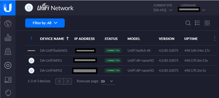
My Environment

Screenshot of 1 UniFi Switch and 2 UniFi NanoHD's adopted in the UniFi Controller
UniFi Devices Adopted in the UniFi Controller

In my environment, the following is true:

  • No devices except a DHCP/DNS server and firewall/router sit on the untagged VLAN of 1.
  • My UniFi devices (including controller, Access Points, and switches) have a separate dedicated management VLAN.

The purpose of having an untagged VLAN of 1 is to allow provisioning of devices that self or auto provision. This network is an isolated network that is heavily controlled via the router and firewall that is running IPS (Intrusion Prevention System) and strict firewall rules.

Normally I wouldn’t even have anything on the untagged VLAN of 1, however a provisioning network is needed. For example when you plug in a UniFi NanoHD, or a UniFi Switch, it’ll grab an IP on the untagged VLAN of 1, and look for a controller to present itself to for adoption.

Best Adoption Method

No matter how simple or complex the environment is I always recommend using the DNS method of adoption.

Most networks have DHCP and DNS, whether it’s for workstations, servers, or IT infrastructure. It’s extremely easy to setup a DNS Host (A) record or an Alias (CNAME) record of “unifi” and have it point to your UniFi Controller.

If you’re using multiple VLANs and subnets, your network must be fully routable from the untagged VLAN of 1, all the way to your UniFi controller.

I highly recommend putting strict firewall rules in place to only allow communication to the UniFi Controller from the untagged VLAN 1.

Conclusion

Following these practices allow you to simplify your UniFi deployment even on extremely large and complex networks, while not straying from keeping your network secure!

Everything is automated, efficient, and ready to use!

Leave a comment and leave me some feedback!

Mar 212020
 
CanaKit Raspberry Pi 4 Case with cables

During a previous project I needed to create a fresh and clean boot partition for a Raspberry Pi. I needed to create the partition layout required for the Raspberry Pi to see and boot a Linux kernel from.

There are many guides on the internet on how to write a Raspberry Pi image (which includes the system-boot partition), but I wanted a clean and fresh partition layout, without the additional partitions containing the Linux operating system.

I was creating a new Micro SD card with the purpose of using an NFS Root for the Raspberry Pi. For those of you that don’t know, you can boot a Raspberry Pi (or Linux computer) from local media, whether it’s a CD, USB Stick, Micro SD, or hard drive, and then have the actual operating system root file system be loaded via NFS. You can also use PXE to boot the kernel requiring no local storage, but that’s beyond the scope of this article.

Raspberry Pi default Partition layout

Below, we’ll look at the default partition layout you’d see on a Raspberry Pi using a prebuild linux image.

Disk /dev/sda: 59.6 GiB, 64021856256 bytes, 125042688 sectors
Units: sectors of 1 * 512 = 512 bytes
Sector size (logical/physical): 512 bytes / 512 bytes
I/O size (minimum/optimal): 512 bytes / 512 bytes
Disklabel type: dos
Disk identifier: 0x97709164
Device     Boot  Start       End   Sectors  Size Id Type
/dev/sda1         8192    532479    524288  256M  c W95 FAT32 (LBA)
/dev/sda2       532480 125042687 124510208 59.4G 83 Linux

I’m using a USB to Micro SD adapter to view the partitions on this card, so it’s being presented to the system as “/dev/sda”. On a normal computer “/dev/sda” is the first hard drive (usually the OS) so be careful when using these commands.

You’ll notice that “/dev/sda1” is the Raspberry Pi boot partition, with an Id of 3, and has the type of “W95 FAT32 (LBA)”.

The second partition which is the filesystem root (which I moved to NFS), is “/dev/sda2”, with an Id of 83, and has a type of “Linux”.

Creating a fresh partition layout with only the boot partition

In this guide we’re going to setup a Micro SD card with a fresh boot partition for the Raspberry Pi from scratch. We are not using an image and we are not using the expansion feature.

We’re going to assume that your destination SD card is empty. If it isn’t, you’ll need to delete all the partitions using “fdisk /dev/device”, and then deleted them with “d”.

Alternatively, to delete existing partition information you can wipe the MBR and partition table with the following command. Replace “/dev/device” with the actual device label for the card. Note that this will render existing data useless and unrecoverable.

dd if=/dev/zero of=/dev/DEVICE bs=512 count=1

Please Note: Make sure you are running this command on the right device. Afterwards, unplug and re-insert the SD card.

Creating the layout

On an empty Micro SD card:

  1. Open fdisk on your card.
    fdisk /dev/sda
  2. Press “n” to create a partition.
  3. Press “p” to make it a primary partition.
  4. Press “1” to make it the first partition in the table.
  5. Press <enter> to accept the default on start sector.
  6. Type +size to choose the size. In my case I want 1GB, so I’ll type “+1G”.
  7. After it’s created, press “a” to make it bootable.
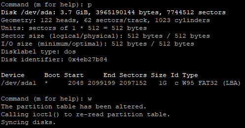
  8. Now we press “p” to print and view the partition table, as shown below.
    Command (m for help): p
    Disk /dev/sda: 3.7 GiB, 3965190144 bytes, 7744512 sectors
    Geometry: 122 heads, 62 sectors/track, 1023 cylinders
    Units: sectors of 1 * 512 = 512 bytes
    Sector size (logical/physical): 512 bytes / 512 bytes
    I/O size (minimum/optimal): 512 bytes / 512 bytes
    Disklabel type: dos
    Disk identifier: 0x4eb27b84
    Device Boot Start End Sectors Size Id Type
    /dev/sda1 * 2048 2099199 2097152 1G 83 Linux
  9. Now we need to set the partition type. Press “t” to set a partition type, choose the partition, and type “c” for “W95 FAT32 (LBA)”.
  10. We’re now left with this partition table.
    Image of a new clean Raspberry Pi Boot Partition Layout
  11. Press “w” to write and save, and exit fdisk.
  12. We now need to format the partition. Run the following command on your device.
    mkfs.vfat /dev/sda1

Finally, you can now set a label to the partition. Ubuntu uses the label “system-boot” whereas Raspbian uses “boot”. You can set it with the following command:

fatlabel /dev/device NEW_LABEL

You now have a clean partition layout that can be used to boot a Raspberry Pi. Remember that this is just the partition layout and the files are still needed from an image or your current running instance. These can simply be copied over.

In my case, I just mounted an old and the new partitions to directories and copied the data over. This allowed me to modify the new boot partition and ultimately make it boot in to an NFS root.

If you need just a simple boot partition, you don’t need to purchase large Micro SD cards.

Mar 212020
 
CanaKit Raspberry Pi 4 case open with Fan Kit and running

In this post you’ll find a list of handy tips, tricks, and commands for your new Raspberry Pi 4.

I’ve been maintaining a document to record these so I can search and re-use them, and figured I’d share them on the blog for others to use as well.

I’m hoping to target both Raspbian and Ubuntu Server for the Raspberry Pi 4. If you have any feedback or input, please leave a comment!

Enable 64-Bit Kernel on Raspbian

Enables 64-bit kernel on Raspbian, however remember that the userspace is still 32-bit.

  1. Run “rpi-update” to make sure you’re running latest firmware and kernel.
    rpi-update
  2. Add “arm_64bit=1” to “/boot/config.txt”
    sudo echo arm_64bit=1 >> /boot/config.txt
  3. Restart

Remove, comment out, or set the value to 0 to go back to a 32-bit kernel.

Get CPU Temperature on Raspbian

Run the command “sudo vcgencmd measure_temp” to get the CPU temperature on Raspbian.

pi@raspberrypi:~ $ sudo vcgencmd measure_temp
temp=38.0'C

Get CPU Temperature on Ubuntu Server

Run the command “paste <(cat /sys/class/thermal/thermal_zone/type) <(cat /sys/class/thermal/thermal_zone/temp) | column -s $’\t’ -t | sed ‘s/(.)..$/.\1°C/'” as root to get the CPU temperature on Ubuntu Server.

root@ubuntu:~# paste <(cat /sys/class/thermal/thermal_zone/type) <(cat /sys/class/thermal/thermal_zone/temp) | column -s $'\t' -t | sed 's/(.)..$/.\1°C/'
cpu-thermal  45.2°C

Add root CA (Certification Authority) certificates to the trust on Raspbian and Ubuntu Server

To add a root CA to your CA trust on your Linux instance, perform the following:

  1. Save your certificate as a friendly-filename.crt (CRT extension is important) and copy to “/usr/local/share/ca-certificates/”.
  2. Run the “update-ca-certificates” command as root or sudo.
    update-ca-certificates

Install Cockpit Remote Web Administration

To install cockpit on your Raspberry Pi, run the following command as root or sudo:

apt install cockpit

After this, login to Cockpit on your Pi by pointring your browser to https://PI-IP-ADDRESS:9090

To install the Target CLI to configure the iSCSI Target

In order to configure the Linux kernel iSCSI target, you need the “targetcli” application/binary.

To install on Raspbian, run the command as root or sudo:

apt install targetcli

To install on Ubuntu Server, run the command as root or sudo:

apt install targetcli-fb

Mar 192020
 
VMware Horizon View Icon

After installing the VMware Horizon Agent on a Physical PC, you may have noticed some issues with USB redirection, audio, and hardware redirection. These issues include not working, or not working in it’s entirety.

On a few occasions I’ve had readers reach out to inform me that they are experiencing these issues. Most recently a reader by the name of “Sascha” reached out and reported issues with audio, particularly the microphone not functioning or being redirected from the VMware Horizon View Client to the Physical PC.

The Fix

In Sascha’s case (along with the other readers), we troubleshot the issue and realized that in each and every case the problem was due to the use of a Windows 10 Profesional license being used. As per the VMware Horizon release notes, a Windows 10 Enterprise license must be used when installing the Horizon Agent on a Physical PC.

Once Sascha and the other users upgrades or installed a Windows 10 Enterprise license, the issues stopped immediately.

This is another reminder that you need an Windows 10 Enterprise license when installing the Horizon Agent on a Physical PC.

Mar 182020
 
vSphere Logo Image

I’ve noticed in a few situations where an ESXi host is marked as “unresponsive” or “disconnected” inside of vCenter due to issues occurring on that host (or connected hardware). This recently happened again with a customer and is why I’m writing this article at this very moment.

In these situations, usually all normal means of managing, connecting, or troubleshooting the host are unavailable. Usually in cases like this ESXi administrators would simply reset the host.

However, I’ve found hosts can often be rescued without requiring an ungraceful restart or reset.

Observations

In these situations, it can be observed that:

  • The ESXi host is in a unresponsive to disconnected state to vCenter Server.
  • Connecting to the ESXi host directly does not work as it either doesn’t acknowledge HTTPS requests, or comes up with an error.
  • Accessing the console of the ESXi host isn’t possible as it appears frozen.
  • While the ESXi host is unresponsive, the virtual machines are still online and available on the network.

Troubleshooting

In the few situations I’ve noticed this occurring, troubleshooting is possible but requires patience. Consider the following:

  • When trying to access the ESXi console, give it time after hitting enter or selecting a value. If there’s issues on the host such as commands pending, tasks pending, or memory issues, the console may actually respond if you give it 30 seconds to 5 minutes after selecting an item.
  • With the above in mind, attempt to enable console access (preferably console and not SSH). The logins may take some time (30 seconds to 5 minutes after typing in the password), but you might be able to gain troubleshooting access.
  • Check the SAN, NAS, and any shared storage… In one instance, there were issues with a SAN and datastore that froze 2 VMs. The Queued commands to the SAN caused the ESXi host to become unresponsive.
  • There may be memory issues with the ESXi instance. The VMs are fine, however an agent, driver, or piece of software may be causing the hypervisor layer to become unresponsive.

If there are storage issues, do what you can. In one of the cases above, we had to access the ESXi console, issue a “kill -9” to the VM, and then restart the SAN. We later found out there was issues with the SAN and corrupted virtual machines. The moment the SAN was restarted, the ESXi host became responsive, connected to the vCenter server and could be managed.

In another instance, on an older version of ESXi there was an HPE agentless management driver/service that was consuming the ESXi hosts memory continuously causing the memory to overflow, the host to fill the swap and become unresponsive. Eventually after gracefully shutting down the VMs, I was able to access the console, kill the service, and the host become responsive.

Mar 182020
 
Raspberry Pi iSCSI Target with external USB drive attached

The Raspberry Pi 4 is a super neat little device that has a whole bunch of uses, and if there isn’t for something you’re looking for you can make one! As they come out with newer and newer generations of the Raspberry Pi, the hardware gets better, faster, and the capabilities greatly improve.

I decided it was time with the newer and powerful Raspberry Pi 4, to try and turn it in to an iSCSI SAN! Yes, you heard that right!

With the powerful quad core processor, mighty 4GB of RAM, and USB 3.0 ports, there’s no reason why this device couldn’t act as a SAN (in the literal sense). You could even use mdadm and configure it as a SAN that performs RAID across multiple drives.

Picture of a Raspberry Pi 4 with External USB 3 HD setup as an iSCSI Target and SAN
Raspberry Pi 4 with External USB 3 HD

In this article, I’m going to explain what, why, and how to (with full instructions) configure your Raspberry Pi 4 as an iSCSI SAN, an iSCSI Target.

Please Note: these instructions also apply to standard Linux PCs and Servers as well, but I’m putting emphasis that you can do this on SBCs like the Raspberry Pi.

A little history…

Over the years on the blog, I’ve written numerous posts pertaining to virtualization, iSCSI, storage, and other topics because of my work in IT. On the side as a hobby I’ve also done a lot of work with SBC (Single Board Computers) and storage.

Some of the most popular posts, while extremely old are:

You’ll notice I put a lot of effort specifically in to “Lio-Target”…

When deploying or using Virtualization workloads and using shared iSCSI storage, the iSCSI Target must support something called SPC-3/SPC-4 Reservations.

SPC-3 and SPC-4 reservations allow a host to set a “SCSI reservation” and reserve the blocks on the storage it’s working with. By reserving the storage blocks, this allows numerous hosts to share the storage. Ultimately this is what allows you to have multiple hosts accessing the same volume. Please keep in mind both the iSCSI Target and the filesystem must support clustered filesystems and multiple hosts.

Originally, most of the open source iSCSI targets including the one that was built in to the Linux kernel did not support SCSI reservations. This resulted in volume and disk corruption when someone deployed a target and connected with multiple hosts.

Lio-Target specifically supported these reservations and this is why it had my focus. Deploying a Lio-target iSCSI target fully worked when using with VMware vSphere and VMware ESXi.

Ultimately, on January 15th, 2011 the iSCSI target in the Linux kernel 2.6.38 was replaced with Lio-target. All new Linux kernels use the Lio-Target as it’s iSCSI target.

What is an iSCSI Target?

An iSCSI target is a target that contains LUNs that you connect to with an iSCSI initiator.

The Target is the server, and the client is the initiator. Once connected to a target, you can directly access volumes and LUNs using iSCSI (SCSI over Internet).

What is it used for?

iSCSI is mostly used as shared storage for virtual environments like VMware vSphere (and VMware ESXi), as well as Hyper-V, and other hypervisors.

It can also be used for containers, file storage, remote access to drives, etc…

Why would I use or need this on the Raspberry Pi 4?

Some users are turning their Raspberry Pi’s in to NAS devices, whynot turn it in to a SAN?

With the powerful processor, 4GB of RAM, and USB 3.0 ports (for external storage), this is a perfect platform to act as a testbed or homelab for shared storage.

For virtual environments, if you wanted to learn about shared storage you could deploy the Raspberry Pi iSCSI target and connect to it with one or more ESXi hosts.

Or you could use this to remotely connect to a disk on a direct block level, although I’d highly recommend doing this over a VPN.

How do you connect to an iSCSI Target?

As mentioned above, you normally connect to an iSCSI Target and volume or LUN using an iSCSI initiator.

Using VMware ESXi, you’d most likely use the “iSCSI Software Adapter” under storage adapters. To use this you must first enable and configure it under the Host -> Configure -> Storage Adapters.

Image of the iSCSI Initiator software adapter configuration on VMware vSphere of an ESXi host.
VMware vSphere Host iSCSI Initiator Software Adapter

Using Windows 10, you could use the iSCSI initiator app. To use this simply search for “iSCSI Initiator” in your search bar, or open it from “Administrative Tools” under the “Control Panel”.

The Windows 10 iSCSI Initiator (iSCSI Properties) window.
Windows 10 iSCSI Initiator (iSCSI Properties)

There is also a Linux iSCSI initiator that you can use if you want to connect from a Linux host.

What’s needed to get started?

To get started using this guide, you’ll need the following:

  • Raspberry Pi 4
  • Ubuntu Server for Raspberry Pi or Raspbian
  • USB Storage (External HD, USB Stick, preferably USB 3.0 for speed)
  • A client device to connect (ESXi, Windows, or Linux)
  • Networking gear between the Raspberry Pi target and the device acting as the initiator

Using this guide, we’re assuming that you have already installed, are using, and have configured linux on the Raspberry Pi (setup accounts, and configured networking).

The Ubuntu Server image for Raspberry Pi comes ready to go out of the box as the kernel includes modules for the iSCSI Target pre-built. This is the easier way to set it up.

These instructions can also apply to Raspbian Linux for Raspberry Pi, however Raspbian doesn’t include the kernel modules pre-built for the iSCSI target and there are minor name differences in the apps. This is more complex and requires additional steps (including a custom kernel to be built).

Let’s get started, here’s the instructions…

If you’re running Raspbian, you need to compile a custom kernel and build the iSCSI Target Core Modules. Please follow my instructions (click here) to compile a custom kernel on Raspbian or Raspberry Pi. When you’re following my custom kernel build guide, in addition after running “make menuconfig”:

  1. Navigate to “Device Drivers”.
  2. Select (using space bar) “Generic Target Core Mod (TCM) and ConfigFS Infrastructure” so that it has an <M> (for module) next to it. Then press enter to open it. Example below.
    <M> Generic Target Core Mod (TCM) and ConfigFS Infrastructure
  3. Select all the options as <M> so that they compile as a kernel module, as shown below.
     --- Generic Target Core Mod (TCM) and ConfigFS Infrastructure
    <M> TCM/IBLOCK Subsystem Plugin for Linux/BLOCK
    <M> TCM/FILEIO Subsystem Plugin for Linux/VFS
    <M> TCM/pSCSI Subsystem Plugin for Linux/SCSI
    <M> TCM/USER Subsystem Plugin for Linux
    <M> TCM Virtual SAS target and Linux/SCSI LDD Fabcric loopback module
    <M> Linux-iSCSI.org iSCSI Target Mode Stack
  4. Save the kernel config and continue following the “compile a custom raspberry pi kernel” guide steps.

If you’re running Ubuntu Server, the Linux kernel was already built with these modules so the action above is not needed.

We’re going to assume that the USB drive or USB stick you’ve installed is available on the system as “/dev/sda” for the purposes of this guide. Also please note that when using the create commands in the entries below, it will create it’s own unique identifiers on your system different from mine, please adjust your commands accordingly.

Let’s start configuring the Raspberry Pi iSCSI Target!

  1. First we need to install the targetcli interface to configure the target.
    As root (or use sudo) run the following command if you’re running Ubuntu Server.
    apt install targetcli-fb
    As root (or use sudo) run the following command if you’re running Raspbian.
    apt install targetcli
  2. As root (or using sudo) run “targetcli”.
    targetcli
    Running the targetcli command
  3. Create an iSCSI Target and Target Port Group (TPG).
    cd iscsi/
    create
    Command to create a TPG iSCSI Target
  4. Create a backstore (the physical storage attached to the Raspberry Pi).
    cd /backstores/block
    create block0 /dev/sda
    Creating an iSCSI Target Backstore command
  5. Create an Access Control List (ACL) for security and access to the Target.
    cd /iscsi/iqn.2003-01.org.linux-iscsi.ubuntu.aarch64:sn.eadcca96319d/tpg1/acls
    create iqn.1991-05.com.microsoft:your.iscsi.initiator.iqn.com
    Creating an ACL inside of targetcli for the iSCSI Target
  6. Add, map, and assign the backstore (block storage) to the iSCSI Target LUN and ACL.
    cd /iscsi/iqn.2003-01.org.linux-iscsi.ubuntu.aarch64:sn.eadcca96319d/tpg1/luns
    create /backstores/block/block0
    Mapping a backstore to LUN and ACL in TargetCLI
  7. Review your configuration.
    cd /
    ls
    Reviewing the configuration in TargetCLI
  8. Save your configuration and exit.
    saveconfig
    exit
    Saving the configuration and exiting the targetcli interface

That’s it, you can now connect to the iSCSI target via an iSCSI initiator on another machine.

For a quick example of how to connect, please see below.

Connect the ESXi Initiator

To connect to the new iSCSI Target on your Raspberry Pi, open up the configuration for your iSCSI Software Initiator on ESXi, go to the targets tab, and add a new iSCSI Target Server to your Dynamic Discovery list.

Add iSCSI Server to the Dynamic Discovery list on the iSCSI Software Initiator on ESXi
ESXi adding iSCSI Target Server (SAN) to iSCSI Software Initiator Dynamic Discovery

Once you do this, rescan your HBAs and the disk will now be available to your ESXi instance.

Connect the Windows iSCSI Initiator

To connect to the new iSCSI Target on Windows, open the iSCSI Initiator app, go to the “Discovery” tab, and click on the “Discover Portal” button.

Adding an iSCSI Target Server to the Windows iSCSI Software Initiator
Add iSCSI Target Server to Windows iSCSI Initiator

In the new window, add the IP address of the iSCSI Target (your Raspberry Pi), and hit ok, then apply.

Now on the “Targets” tab, you’ll see an entry for the discovered target. Select it, and hit “Connect”.

The targets list on Windows iSCSI Software Initiator
Windows iSCSI Initiator Targets List

You’re now connected! The disk will show up in “Disk Management” and you can now format it and use it!

Here’s what an active connection looks like.

The Microsoft iSCSI Initiator window open, showing an active connection to an iSCSI target, and iSCSI disk
Windows 10 iSCSI Initiator connect to iSCSI Target presenting a disk

That’s all folks!

Conslusion

There you have it, you now have a beautiful little Raspberry Pi 4 acting as a SAN and iSCSI Target providing LUNs and volumes to your network!

Picture of Raspberry Pi 4 iSCSI Target running Ubuntu Server with External USB 3 HD
Raspberry Pi 4 iSCSI Target with External USB 3 HD

Leave a comment and let me know how you made out or if you have any questions!

Mar 172020
 
Picture of Raspberry Pi 4 box and Raspberry Pi 4 board below box

So you’ve got a shiny new Raspberry Pi 4 and you need to compile a fresh and custom Linux kernel on Raspbian. You might need some features, some kernel modules, or you just want to compile the latest version from source.

I’m doing various projects (and blog posts) and with one of the projects, I found I needed to compile and enable a kernel module that wasn’t built in to the latest Raspbian image for the Pi 4.

This guide is also great if you just want to learn how to compile the kernel yourself!

Instructions

You may find that this guide is slightly different that the guide on the Raspberry Pi website and other sites. I like to append a unique name to the kernel version so I don’t have to touch the existing kernels. This allows me to revert or run multiple different custom kernels and switch back and forth.

Please note: You must be using a 32-bit kernel (or the default Raspbian kernel) to compile a new 32-bit kernel. You will not be able to compile a new kernel (32-bit or 64-bit) if you have booted in to the 64-bit kernel using the “arm_64bit=1” switch in “config.txt”. I’ve tried to compile a 64-bit kernel on Raspbian, but have not yet been able to do so. I’ll update with a new post once I figure it out.

And don’t forget, this can take some time and is CPU intensive. I installed a fan to help cool the temperatures while compilling!

This guide will compile a 32-bit kernel.

  1. Install some packages required to building and compiling.
    apt install raspberrypi-kernel-headers build-essential bc git wget bison flex libssl-dev make libncurses-dev
  2. Create a directory for us to work in.
    mkdir kernel
    cd kernel
  3. Clone the latest kernel sources using GIT.
    git clone --depth=1 https://github.com/raspberrypi/linux
  4. Setup the kernel configuration for compiling.
    cd linux
    KERNEL=kernel7l
    make bcm2711_defconfig
  5. Make any changes you want to the kernel configuration and append a friendly local version name by using make menuconfig.
    make menuconfig

    To change the friendly name, navigate to “General Setup” and select/modify “Local Version – append to kernel release”.
    (-v7lstephen) Local version - append to kernel release
  6. Compile the kernel, modules, and device tree blobs.
    make -j4 zImage modules dtbs
  7. Install compiled modules.
    make modules_install
  8. Copy the kernel, modules, and other files to the boot filesystem.
    cp arch/arm/boot/dts/*.dtb /boot/
    cp arch/arm/boot/dts/overlays/*.dtb* /boot/overlays/
    cp arch/arm/boot/dts/overlays/README /boot/overlays/
    cp arch/arm/boot/zImage /boot/kernel-stephen.img
  9. Configure the PI to boot using the new kernel by modifying and adding the below line to “/boot/config.txt”.
    kernel=kernel-stephen.img
  10. Reboot!

Bam! You’re now using your shiny new Linux kernel on the Raspberry Pi 4!

To rescue a failed build or if the Pi won’t boot

If for some reason the Pi won’t boot, you can recover the previous kernel since we used a new name with the new kernel.

To rescue the image you’ll need another Linux computer that can read the Micro-SD card.

  1. Insert the Micro-SD Card in the computer.
  2. Mount the /boot/ filesystem on the Micro SD card to a local directory.
  3. Edit the “config.txt” file and remove the “kernel=kernel-name.img” line we made above, or alternatively comment it out by inserting a “#” before the line.
    #kernel=kernel-stephen.img
  4. Save the file.
  5. Unmount the partition.
  6. Insert in the Raspberry Pi and boot!

You should now be back up and running and should be able to try again!

Leave some feedback and let me know if it worked for you. In the future I’ll be doing another post on compiling a 64-bit kernel for the Raspberry Pi 4 on Raspbian.