In this video, I sit down and chat with Joe Cooper to find out “What’s the deal with TPMs, vTPMs, vSphere NKP, and VDI?”
We’ll be talking about everything from Physical TPMs, to Virtual TPM (vTPM), VMware vSphere Native Key Provider (NKP), and specialized workloads such as Virtual Desktop Infrastructure (VDI).
A big thank you to Joe Cooper for co-producing and joining me on this video.
Recently I came across a new issue and scenario in an environment where when trying to perform a vLCM function like remediation or staging, resulted in vLCM Remediation Stuck at 2%.
When this occured, all the systems on the VMware vCenter Appliance were functioning with no errors or failed tasks. If you start the process and it gets stuck on 2%, it can sit there for over an hour without failing.
Before we jump in to this issue, let’s first review the process that occurs with vLCM. I will simply this for purposes of explaining what occurs.
Normally, when kicking off a vLCM action such as remediation, you’d see a workflow similar to this when starting vLCM remediation:
VMware vSphere Task Created: “Remediate Cluster” (if remediating a cluster)
Compliance Check on vSphere cluster
Remediation of Hosts
ESXi Host VM Evacuation (Requires DRS)
ESXi Host Enters Maintenance Mode
ESXi Host updates applied
Restart (if required)
ESXi Host Exits Maintenance Mode
Compliance Check
vLCM continues to remaining hosts in the cluster or completes if no hosts remaining
The Issue
When this issue occurs, both vLCM Remediation and vLCM Staging will result in the task (item #1) listed above “Remediate Cluster” or “Staging Cluster” getting stuck at 2%, and none of the steps in the workflow after that occur.
The process gets stuck before compliance check, or even maintenance mode.
The Solution
After troublehsooting, reviewing logs, all I could see was some timeouts inside of the vLCM logs on the vCenter Server appliance (vCSA).
Seeing timeouts with no additional information to work with, I turned to reviewing the network configuration on the vCenter server and ESXi hosts.
It turns out that the vCenter server was pointed to the single DNS server that was offline. After correcting and updating the DNS settings on the vCenter appliance, the issue was completely resolved.
A friendly reminder that it’s time to upgrade (or start planning) since VMware vSphere 7 is reaching end of life on October 2nd, 2025. This means that if you’re running VMware vSphere 7 in your environment, VMware will no longer release updates, security patches, and/or provide support for your environment.
Please note: You will require an active subscription to be entitled to, and also have access to the updates and upgrades. You’ll also want to check the interopability and HCLs to make sure your hardware is supported.
Upgrade Path for VMware vSphere Standard, vSphere Enterprise Plus)
It’s never been a better time to upgrade (literally) with the pending EOL. For customers running VMware vSphere Standard (VVS) or those with with VMware vSphere Enterprise Plus subscriptions, your upgrade path will be to vSphere 8.
Upgrade Path for VMware vSphere Foundation, VMware Cloud Foundation
For customers who are currently licensed for VMware vSphere Foundation (VVF), or VMware Cloud Foundation (VCF) subscriptions and licensing, you’ll be able to either upgrade to vSphere 8 products, or the nice and shiny new VMware vSphere Foundation 9 (VVF 9), or VMware Cloud Foundation 9 (VCF 9).
Upgrading VMware vCenter Server
You’ll always want to upgrade your VMware vCenter instance first (except when using VCF, as the procedures are different and out of the scope of this post). Just a reminder that this is a generally easy process where, using the installer, a new VM is deployed using the vCenter Server Installer ISO. The workflow then migrates and upgrades your data to the new appliance, shutting down the old.
Always make sure to perform a VAMI file-based backup, in addition to a snapshot of the previous vCSA appliance. I usually disabled DRS and HA before the backup/snapshot as well, as this allows easier recovery in the event of a failed vCenter upgrade.
Upgrading VMware ESXi Hosts
When it comes to your VMware ESXi hosts (as I recommend to customers), use vLCM (VMware Lifecycle Management) and Image Based Updates if possible as this makes the upgrade a breeze (and supports QuickBoot). Note that baselines updates are deprecated.
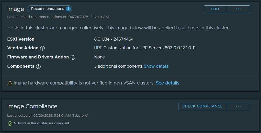
If the hardware in your cluster comes from a single vendor (example, HPE, Cisco, Dell), you can use cluster based (and cluster focused) vLCM Image based updates.
When you change your cluster to Image based Updates (irreversable for the cluster once created), you’ll be able to choose your target ESXi version, specify the Vendor add-on, and then customize additional components (such as adding the NVIDIA vGPU Host Driver and GPU Management daemon, storage plugins, etc).
After creating your image, you’ll then be able to apply it to your hosts. This can be used for minor updates, and also larger upgrades (such as VMware ESXi 7 to 8).
Here’s a fun quick VDI Gaming Demo with NVIDIA vGPU and Omnissa Horizon 8, using an NVIDIA L4 GPU and the L4-12Q Profile.
This video is just for fun, and is just to show some of the capabilities of the technology, hardware, and software, in this case, with Cloud Gaming.
The NVIDIA vGPU solution provides the ability to “slice” and create multiple Virtual GPU (vGPU) devices for your Virtual Machines and Virtual workloads.
In this video:
Quick Introduction to NVIDIA vGPU with Omnissa Horizon 8
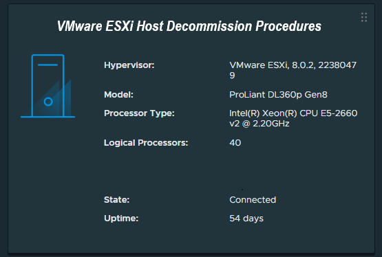
While most of us frequently deploy new ESXi hosts, a question and task not oftenly discussed is how to properly decommission a VMware ESXi host.
Some might be surprised to learn that you cannot simply just power down and remove the host from the vCenter server, as there are a number of steps that must be taken beforehand to ensure a proper successful decommission. Properly decommissioning the ESXi host avoids orphaned objects in the vCenter database, which can sometimes cause problems in the future.
Today we’ll go over how to properly decommission a VMware ESXi host in an environment with VMware vCenter Server.
The Process – How to decommission ESXi
We will detail the process and considerations to decommission an ESXi host. We will assume that you have since migrated all your VMs, templates, and files from the host, and it contains no data that requires backup or migration.
Please read further for extended procedures and more information.
Enter Maintenance Mode
We enter maintenance mode to confirm that no VMs are running on the host. You can simply right click the host, and enter maintenance mode.
Remove Host from vDS Switches
You must gracefully remove the host from any vDS switches (VMware Distributed Switches) before removing the host from vCenter Server.
You can create a standard vSwitch and migrate vmk (VMware Kernel) adapters from the vDS switch to standard vSwitch, to maintain communication with the vCenter server and other networks.
Please Note: If you are using vDS switches for iSCSI connectivity, you must gracefully develop a plan to deal with this beforehand, either by unmounting/detaching the iSCSI LUNs on the vDS before removing the switch, or gracefully migrating the vmk adapters to a standard vSwitch, using MPIO to avoid losing connectivity during the process.
Unmount and Detach iSCSI LUNs
You can now proceed to unmount and detach iSCSI LUNs from the selected system:
Unmount the iSCSI LUN(s) from the host
Detach the iSCSI LUN(s) from the host
You will unmount only on the selected host to be decommissioned, and then detach the LUNs (again only on the host you are decommissioning).
Move Host from Cluster to Datacenter as standalone host
While this may not be required, I usually do this to let vSphere Cluster Services (HA/DRS) adjust for the host removal, and also deal with reconfiguration of the HA agent on the ESXi Host. You can simply move the host from the cluster to the parent datacenter level.
Remove Host from Inventory
Once the host has been moved and a moment or two have elapsed, you can now proceed to remove the host from inventory.
While the host is powered on and still connected to vCenter, right click on the host and choose “Remove from Inventory”. This will gracefully remove objects from vCenter, and also uninstall the HA agent from the ESXi host.
Host Repurposing
At this point, you can now log directly on to the ESXi host using the local root password, and shutdown the host.
This website uses cookies to improve your experience. We'll assume you're ok with this, but you can opt-out if you wish.
Do you accept the use of cookies and accept our privacy policy? AcceptRejectCookie and Privacy Policy
Privacy & Cookies Policy
Privacy Overview
This website uses cookies to improve your experience while you navigate through the website. Out of these cookies, the cookies that are categorized as necessary are stored on your browser as they are essential for the working of basic functionalities of the website. We also use third-party cookies that help us analyze and understand how you use this website. These cookies will be stored in your browser only with your consent. You also have the option to opt-out of these cookies. But opting out of some of these cookies may have an effect on your browsing experience.