May 012021
 
Picture of NVMe Storage Server Project

For over a year and a half I have been working on building a custom NVMe Storage Server for my homelab. I wanted to build a high speed storage system similar to a NAS or SAN, backed with NVMe drives that provides iSCSI, NFS, and SMB Windows File Shares to my network.

The computers accessing the NVMe Storage Server would include VMware ESXi hosts, Raspberry Pi SBCs, and of course Windows Computers and Workstations.

The focus of this project is on high throughput (in the GB/sec) and IOPS.

The current plan for the storage environment is for video editing, as well as VDI VM storage. This can and will change as the project progresses.

The History

More and more businesses are using all-flash NVMe and SSD based storage systems, so I figured there’s no reason why I can’t have build and have my own budget custom all NVMe flash NAS.

This is the story of how I built my own NVMe based Storage Server.

The first version of the NVMe Storage Server consisted of the IO-PEX40152 card with 4 x 2TB Sabrent Rocket 4 NVMe drives inside of an HPE Proliant DL360p Gen8 Server. The server was running ESXi with TrueNAS virtualized, and the PCIe card passed through to the TrueNAS VM.

The results were great, the performance was amazing, and both servers had access to the NFS export via 2 x 10Gb SFP+ networking.

There were three main problems with this setup:

  1. Virtualized – Once a month I had an ESXi PSOD. This was either due to overheating of the IO-PEX40152 card because of modifications I made, or bugs with the DL360p servers and PCIe passthrough.
  2. NFS instead of iSCSI – Because TrueNAS was virtualized inside of the host that was using it for storage, I had to use NFS since the host virtualizing TrueNAS would also be accessing the data on the TrueNAS VM. When shutting down the host, you need to shut down TrueNAS first. NFS disconnects are handled way healthier than iSCSI disconnects (which can cause corruption even if no files are being used).
  3. CPU Cores maxed on data transfer – When doing initial testing, I was maxing out the CPU cores assigned to the TrueNAS VM because the data transfers were so high. I needed a CPU and setup that was better fit.

Version 1 went great, but you can see some things needed to be changed. I decided to go with a dedicated server, not virtualize TrueNAS, and go for a newer CPU with a higher Ghz speed.

And so, version 2 was born (built). Keep reading and scrolling for pictures!

The Hardware

On version 2 of the project, the hardware includes:

Notes on the Hardware:

  • While the ML310e Gen8 v2 server is a cheap low entry server, it’s been a fantastic team member of my homelab.
  • HPE Dual 10G Port 560SFP+ adapters can be found brand new in unsealed boxes on eBay at very attractive prices. Using HPE Parts inside of HPE Servers, avoids the fans from spinning up fast.
  • The ML310e Gen8 v2 has some issues with passing through PCIe cards to ESXi. Works perfect when not passing through.

The new NVMe Storage Server

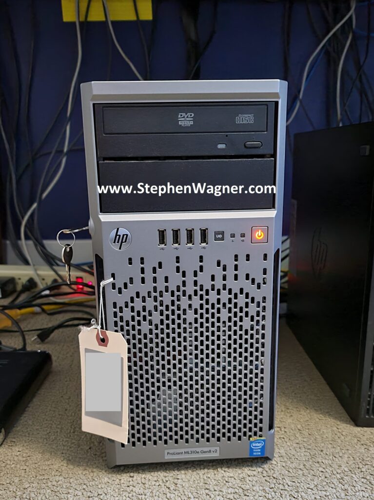
I decided to repurpose an HPE Proliant ML310e Gen8 v2 Server. This server was originally acting as my Nvidia Grid K1 VDI server, because it supported large PCIe cards. With the addition of my new AMD S7150 x2 hacked in/on to one of my DL360p Gen8’s, I no longer needed the GRID card in this server and decided to repurpose it.

Picture of an HPe ML310e Gen8 v2 with NVMe Storage
HPe ML310e Gen8 v2 with NVMe Storage

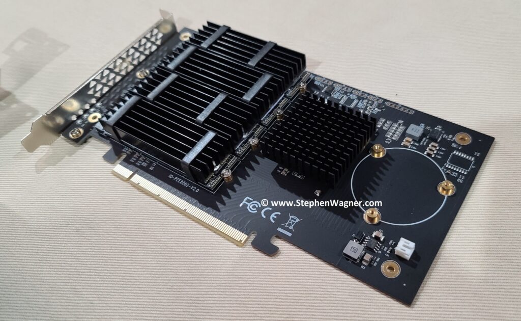
I installed the IOCREST IO-PEX40152 card in to the PCIe 16x slot, with 4 x 2TB Sabrent Rocket 4 NVME drives.

Picture of IOCREST IO-PEX40152 with GLOTRENDS M.2 NVMe SSD Heatsink on Sabrent Rocket 4 NVME
IOCREST IO-PEX40152 with GLOTRENDS M.2 NVMe SSD Heatsink on Sabrent Rocket 4 NVME

While the server has a PCIe 16x wide slot, it only has an 8x bus going to the slot. This means we will have half the capable speed vs the true 16x slot. This however does not pose a problem because we’ll be maxing out the 10Gb NICs long before we max out the 8x bus speed.
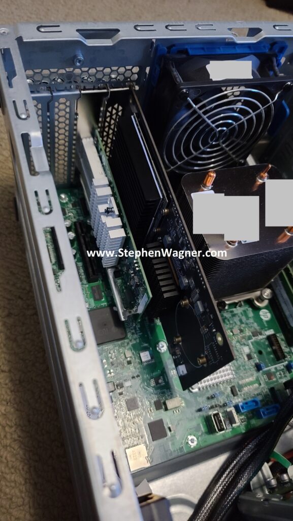
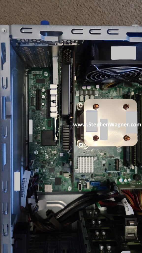
I also installed an HPE Dual Port 560SFP+ NIC in to the second slot. This will allow a total of 2 x 10Gb network connections from the server to the Ubiquiti UniFi US-16-XG 10Gb network switch, the backbone of my network.
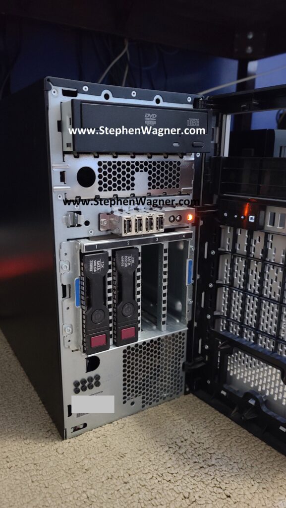
The Server also have 4 x Hot Swappable HD bays on the front. When configured in HBA mode (via the BIOS), these are accessible by TrueNAS and can be used. I plan on populating these with 4 x 4TB HPE MDL SATA Hot Swappable drives to act as a replication destination for the NVMe pool and/or slower magnetic long-term storage.

Front view of HPE ML310e Gen8 v2 with Hotswap Drive bays
HPE ML310e Gen8 v2 with Hotswap Drive bays

I may also try to give WD RED Pro drives a try, but I’m not sure if they will cause the fans to speed up on the server.

TrueNAS Installation and Configuration

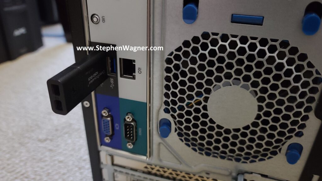
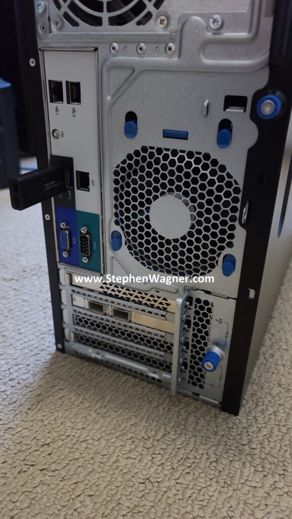
For the initial Proof-Of-Concept for version 2, I decided to be quick and dirty and install it to a USB stick. I also waited until I installed TrueNAS on to the USB stick and completed basic configuration before installing the Quad NVMe PCIe card and 10Gb NIC. I’m using a USB 3.0 port on the back of the server for speed, as I can’t verify if the port on the motherboard is USB 2 or USB 3.

Picture of a TrueNAS USB Stick on HPE ML310e Gen8 v2
TrueNAS USB Stick on HPE ML310e Gen8 v2

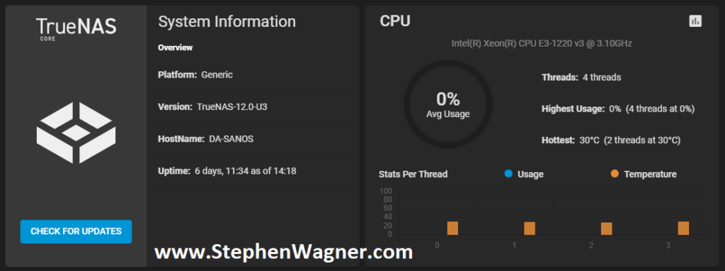
TrueNAS installation worked without any problems whatsoever on the ML310e. I configured the basic IP, time, accounts, and other generic settings. I then proceeded to install the PCIe cards (storage and networking).

Screenshot of TrueNAS Dashboard Installed on NVMe Storage Server
TrueNAS Installed on NVMe Storage Server

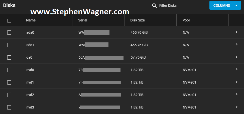
All NVMe drives were recognized, along with the 2 HDDs I had in the front Hot-swap bays (sitting on an HP B120i Controller configured in HBA mode).

Screenshot of available TrueNAS NVMe Disks
TrueNAS NVMe Disks

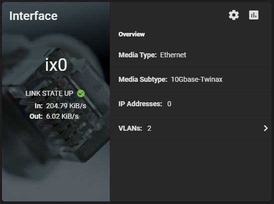
The 560SFP+ NIC also was detected without any issues and available to configure.

Dashboard Screenshot of TrueNAS 560SFP+ 10Gb NIC
TrueNAS 560SFP+ 10Gb NIC

Storage Configuration

I’ve already done some testing and created a guide on FreeNAS and TrueNAS ZFS Optimizations and Considerations for SSD and NVMe, so I made sure to use what I learned in this version of the project.

I created a striped pool (no redundancy) of all 4 x 2TB NVMe drives. This gave us around 8TB of usable high speed NVMe storage. I also created some datasets and a zVOL for iSCSI.

Screenshot of NVMe TrueNAS Storage Pool with Datasets and zVol
NVMe TrueNAS Storage Pool with Datasets and zVol

I chose to go with the defaults for compression to start with. I will be testing throughput and achievable speeds in the future. You should always test this in every and all custom environments as the results will always vary.

Network Configuration

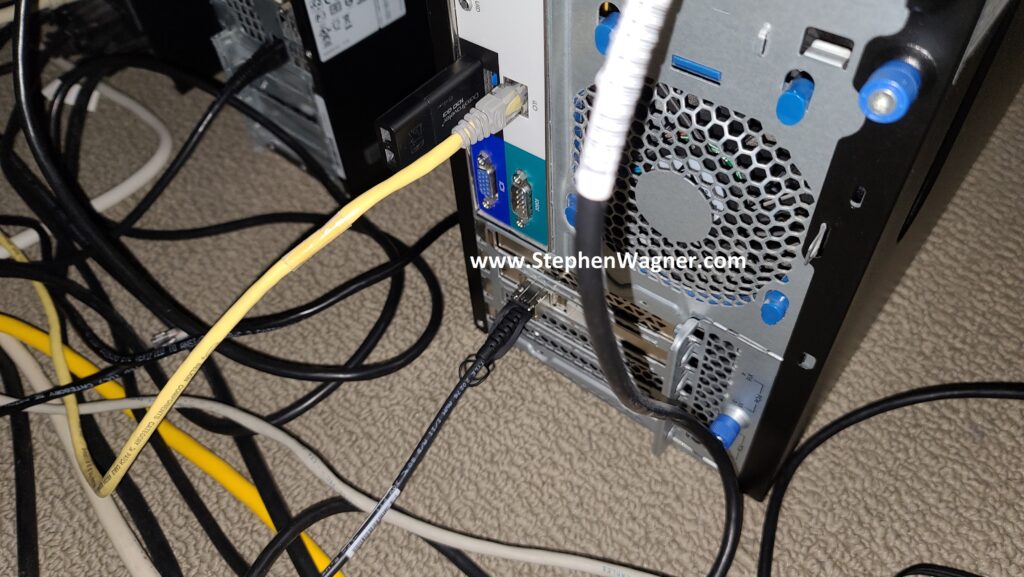
Initial configuration was done via the 1Gb NIC connection to my main LAN network. I had to change this as the 10Gb NIC will be directly connected to the network backbone and needs to access the LAN and Storage VLANs.

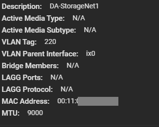
I went ahead and configured a VLAN Interface on VLAN 220 for the Storage network. Connections for iSCSI and NFS will be made on this network as all my ESXi servers have vmknics configured on this VLAN for storage. I also made sure to configure an MTU of 9000 for jumbo frames (packets) to increase performance. Remember that all hosts must have the same MTU to communicate.

Screenshot of 10Gb NIC on Storage VLAN
10Gb NIC on Storage VLAN

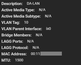
Next up, I had to create another VLAN interface for the LAN network. This would be used for management, as well as to provide Windows File Share (SMB/Samba) access to the workstations on the network. We leave the MTU on this adapter as 1500 since that’s what my LAN network is using.

Screenshot of 10Gb NIC on LAN VLAN
10Gb NIC on LAN VLAN

As a note, I had to delete the configuration for the existing management settings (don’t worry, it doesn’t take effect until you hit test) and configure the VLAN interface for my LANs VLAN and IP. I tested the settings, confirmed it was good, and it was all setup.

At this point, only the 10Gb NIC is now being used so I went ahead and disconnected the 1Gb network cable.

Sharing Setup and Configuration

It’s now time to configure the sharing protocols that will be used. As mentioned before, I plan on deploying iSCSI, NFS, and Windows File Shares (SMB/Samba).

iSCSI and NFS Configuration

Normally, for a VMware ESXi virtualization environment, I would always usually prefer iSCSI based storage, however I also wanted to configure NFS to test throughput of both with NVMe flash storage.

Earlier, I created the datasets for all my my NFS exports and a zVOL volume for iSCSI.

Note, that in order to take advantage of the VMware VAAI storage directives (enhancements), you must use a zVOL to present an iSCSI target to an ESXi host.

For NFS, you can simply create a dataset and then export it.

For iSCSI, you need to create a zVol and then configure the iSCSI Target settings and make it available.

SMB (Windows File Shares)

I needed to create a Windows File Share for file based storage from Windows computers. I plan on using the Windows File Share for high-speed storage of files for video editing.

Using the dataset I created earlier, I configured a Windows Share, user accounts, and tested accessing it. Works perfect!

Connecting the host

Connecting the ESXi hosts to the iSCSI targets and the NFS exports is done in the exact same way that you would with any other storage system, so I won’t be including details on that in this post.

We can clearly see the iSCSI target and NFS exports on the ESXi host.

Screenshot of TrueNAS NVMe iSCSI Target on VMware ESXi Host
TrueNAS NVMe iSCSI Target on VMware ESXi Host
Screenshot of NVMe iSCSI and NFS ESXi Datastores
NVMe iSCSI and NFS ESXi Datastores

To access Windows File Shares, we log on and map the network share like you would normally with any file server.

Testing

For testing, I moved (using Storage vMotion) my main VDI desktop to the new NVMe based iSCSI Target LUN on the NVMe Storage Server. After testing iSCSI, I then used Storage vMotion again to move it to the NFS datastore. Please see below for the NVMe storage server speed test results.

Speed Tests

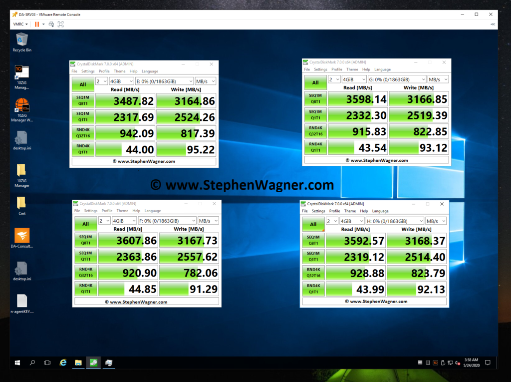
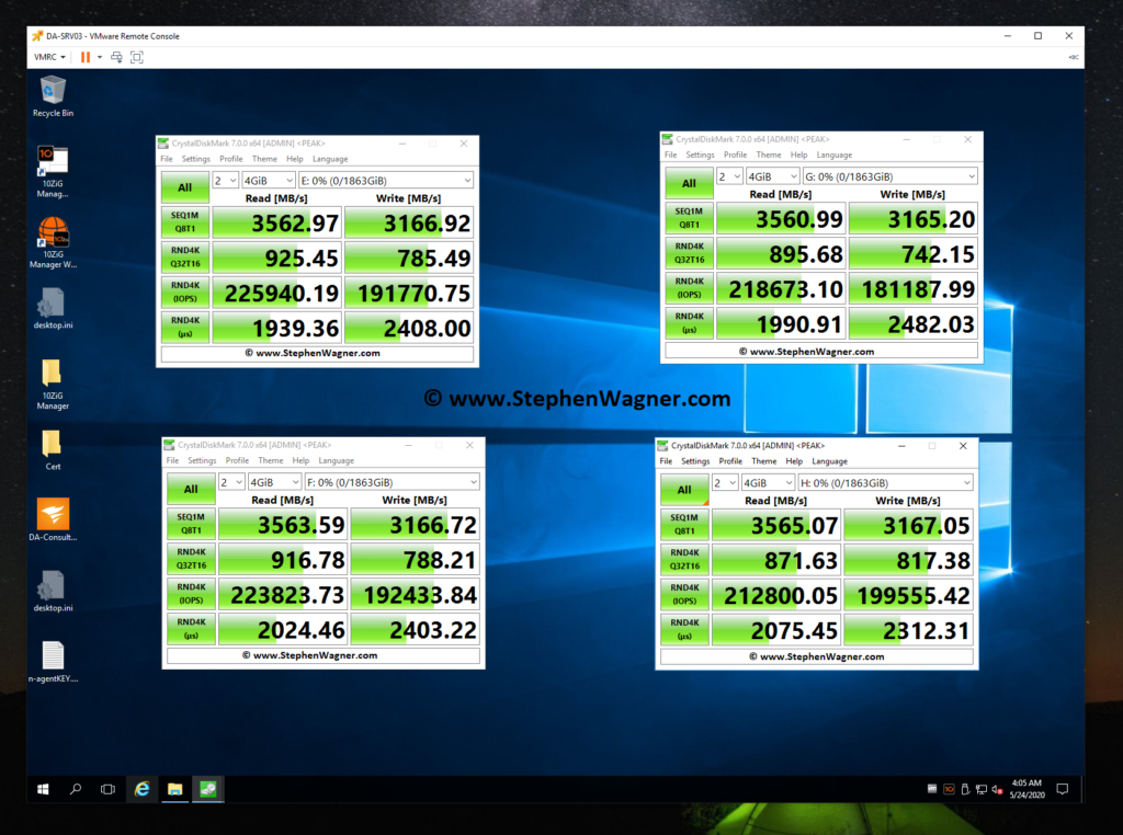
Just to start off, I want to post a screenshot of a few previous benchmarks I compiled when testing and reviewing the Sabrent Rocket 4 NVMe SSD disks installed in my HPE DL360p Gen8 Server and passed through to a VM (Add NVMe capability to an HPE Proliant DL360p Gen8 Server).

Screenshot of CrystalDiskMark testing an IOCREST IO-PEX40152 and Sabrent Rocket 4 NVME SSD for speed
CrystalDiskMark testing an IOCREST IO-PEX40152 and Sabrent Rocket 4 NVME SSD
Screenshot of CrystalDiskMark testing IOPS on an IOCREST IO-PEX40152 and Sabrent Rocket 4 NVME SSD
CrystalDiskMark testing IOPS on an IOCREST IO-PEX40152 and Sabrent Rocket 4 NVME SSD

Note, that when I performed these tests, my CPU was maxed out and limiting the actual throughput. Even then, these are some fairly impressive speeds. Also, these tests were directly testing each NVMe drive individually.

Moving on to the NVMe Storage Server, I decided to test iSCSI NVMe throughput and NFS NVMe throughput.

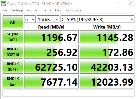
I opened up CrystalDiskMark and started a generic test, running a 16GB test file a total of 6 times on my VDI VM sitting on the iSCSI NVMe LUN.

Screenshot of NVMe Storage Server iSCSI Benchmark with CrystalDiskMark
NVMe Storage Server iSCSI Benchmark with CrystalDiskMark

You can see some impressive speeds maxing out the 10Gb NIC with crazy performance of the NVME storage:

  • 1196MB/sec READ
  • 1145.28MB/sec WRITE (Maxing out the 10GB NIC)
  • 62,725.10 IOPS READ
  • 42,203.13 IOPS WRITE

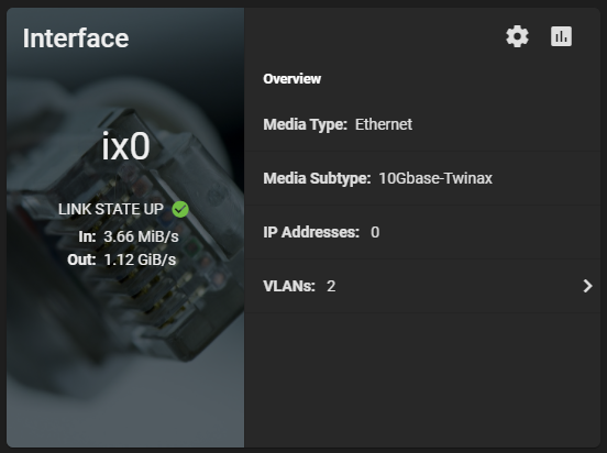
Additionally, here’s a screenshot of the ix0 NIC on the TrueNAS system during the speed test benchmark: 1.12 GiB/s.

Screenshot of TrueNAS NVME Maxing out 10Gig NIC
TrueNAS NVME Maxing out 10Gig NIC

And remember this is with compression. I’m really excited to see how I can further tweak and optimize this, and also what increases will come with configuring iSCSI MPIO. I’m also going to try to increase the IOPS to get them closer to what each individual NVMe drive can do.

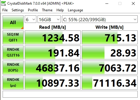
Now on to NFS, the results were horrible when moving the VM to the NFS Export.

Screenshot of NVMe Storage Server NFS Benchmark with CrystalDiskMark
NVMe Storage Server NFS Benchmark with CrystalDiskMark

You can see that the read speed was impressive, but the write speed was not. This is partly due to how writes are handled with NFS exports.

Clearly iSCSI is the best performing method for ESXi host connectivity to a TrueNAS based NVMe Storage Server. This works perfect because we’ll get the VAAI features (like being able to reclaim space).

iSCSI MPIO Speed Test

This is more of an update… I was finally able to connect, configure, and utilize the 2nd 10Gbe port on the 560SFP+ NIC. In my setup, both hosts and the TrueNAS storage server all have 2 connections to the switch, with 2 VLANs and 2 subnets dedicated to storage. Check out the before/after speed tests with enabling iSCSI MPIO.
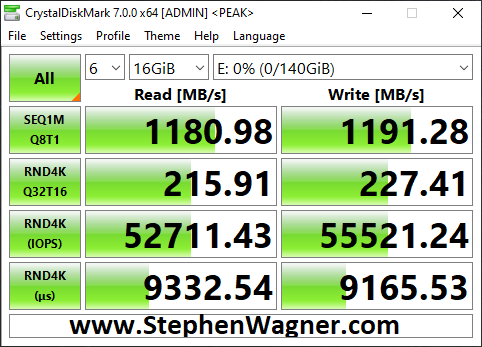
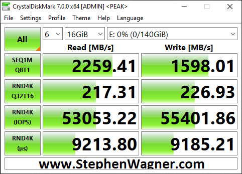
As you can see I was able to essentially double my read speeds (again maxing out the networking layer), however you’ll notice that the write speeds maxed out at 1598MB/sec. I believe we’ve reached a limitation of the CPU, PCIe bus, or something else inside of the server. Note, that this is not a limitation of the Sabrent Rocket 4 NVME drives, or the IOCREST NVME PCIe card.

Moving Forward

I’ve had this configuration running for around a week now with absolutely no issues, no crashes, and it’s been very stable.

Using a VDI VM on NVMe backed storage is lightning fast and I love the experience.

I plan on running like this for a little while to continue to test the stability of the environment before making more changes and expanding the configuration and usage.

Future Plans (and Configuration)

  • Drive Bays
    • I plan to populate the 4 hot-swappable drive bays with HPE 4TB MDL drives. Configured with RaidZ1, this should give me around 12TB usable storage. I can use this for file storage, backups, replication, and more.
  • NVMe Replication
    • This design was focused on creating non-redundant extremely fast storage. Because I’m limited to a total of 4 NVMe disks in this design, I chose not to use RaidZ and striped the data. If one NVMe drive is lost, all data is lost.
    • I don’t plan on storing anything important, and at this point the storage is only being used for VDI VMs (which are backed up), and Video editing.
    • If I can populate the front drive bays, I can replicate the NVMe storage to the traditional HDD storage on a frequent basis to protect against failure to some level or degree.
  • Version 3 of the NVMe Storage Server
    • More NVMe and Bigger NVMe – I want more storage! I want to test different levels of RaidZ, and connect to the backbone at even faster speeds.
    • NVME Drives with PLP (Power Loss Prevention) for data security and protection.
    • Dual Power Supply

Let me know your thoughts and ideas on this setup!
Apr 122020
 
Picture of Raspberry Pi 4 box and Raspberry Pi 4 board below box

If you’re worried about destroying your SD Cards, need some more space, or just want to learn something new, I’m going to show you how to use an NFS root for the Raspberry Pi 4.

When you use an NFS Root with your Raspberry Pi, it stores the entire root filesystem on a remote NFS export (think of it as a network filesystem share). This means you’ll have as much space as the NFS export, and you’ll probably see way faster performance since it’ll be running at 1Gb/sec instead of the speed of the SD Card.

This also protects your SD card, as the majority of the reading and writing is performed on the physical storage of the NFS export, instead of the SD card in the Pi which has limited reads and writes.

What you’ll need

To get started, you’ll need:

  • Raspberry Pi 4
  • Ubuntu or Raspbian for Raspberry Pi 4 Image
  • A small SD card for the Boot Partition (1-2GB)
  • SD card for the Raspberry Pi Linux image
  • Access to another Linux system (workstation, or a Raspberry Pi)

There are multiple ways to do this, but I’m providing instructions on the easiest way it was for me to do this with the resources I had immediately available.

Instructions

To boot your Raspberry Pi 4 from an NFS root, multiple steps are involved. Below you’ll find the summary, and further down you’ll find the full instructions. You can click on an item below to go directly to the section.

The process:

  1. Write the Linux image to an SD Card
  2. Create boot SD Card for NFS Root
  3. Prep the Linux install for NFS Root
  4. Create the NFS Export
  5. Copy the Linux install to the NFS Export
  6. Copy and Modify the boot SD Card to use NFS Root
  7. Boot using SD Card and test NFS Root

See below for the individual instructions for each step.

Write the Linux image to an SD Card

First, we need to write the SD Card Linux image to your SD card. You’ll need to know which device your SD card will appear to your computer. In my case it was /dev/sdb, make sure you verify the right device or you could damage your current Linux install.

  1. Download Ubuntu or Raspbian for Raspberry Pi.
  2. unzip or unxz depending on distribution to uncompress the image file.
  3. Write the SD card image to SD card.
    dd if=imagename.img of=/dev/sdb bs=4M

You now have an SD Card Linux install for your Raspberry Pi. We will later modify and then copy this to the NFS root and boot SD card.

Create boot SD Card for NFS Root

In this step, we’re going to create a bootable SD card that contains the Linux kernel and other needed files for the Raspberry Pi to boot.

This card will be installed in the Pi, load the kernel, and then kick off the boot process to load the NFS root.

I previously created a post to create a boot partition layout for a Raspberry Pi. Please follow those instructions to complete this step.

Later on in this guide, you’ll be copying the boot partition from the SD Card Linux image, on to this newly created boot SD Card for the NFS Root.

Prep the Linux install for NFS Root

There’s a few things we have to do to prep the Ubuntu or Raspbian Linux install to be usable as an NFS Root.

  1. Boot the Raspbian or Ubuntu SD Card you create in the first step on your Raspberry Pi.
  2. Complete the first boot procedures. Create your account, and complete the setup.
  3. Enable and confirm SSH is working so you can troubleshoot.
  4. Install the NFS client files using the following command:
    apt install nfs-common
  5. Open the /etc/network/interfaces file, and add the following line so that the Pi only get’s an IP once during boot:
    iface eth0 inet manual
  6. Modify your /etc/fstab entries to reflect the NFS root and the new boot SD card as per below.

For step 6, we need to modify the /etc/fstab entry for the root fs. It is different depending on whether you’re using Ubuntu or Raspbian.

For Raspbian, your /etc/fstab should look like this:

proc /proc proc defaults 0 0
LABEL=boot /boot vfat defaults 0 2
NFS-SERVER-IP:/nfs-export/PI-Raspbian / nfs defaults 0 0

For Ubuntu, your /etc/fstab should look like this:

LABEL=system-boot /boot/firmware vfat defaults 0 2
/dev/nfs / nfs defaults 0 0

After you do this, the Linux SD image may not boot again if directly installed in the Raspberry Pi, so make sure you’ve made the proper modifications before powering it down.

Create the NFS Export

In my case I used a Synology DS1813+ as an NFS server to host my Raspberry Pi NFS root images. But you can use any Linux server to host it.

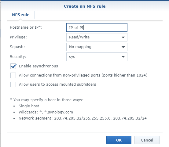
If you’re using a synology disk station, create a shared folder, disable the recycling bin, leave everything else default. Head over to the “NFS Permissions” tab and create an ACL entry for your PI and workstations. You can also add a network segment for your entire network (ex. 192.168.0.0/24″) instead of specifying individual IPs.

Screenshot of Synology Create NFS rule for ACL
Create an NFS ACL Rule for Synology NFS Access

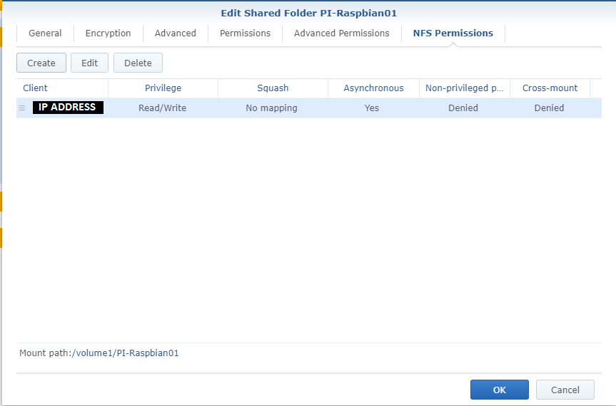
Once you create an entry, it’ll look like this. Note the “Mount path” in the lower part of the window.

Screenshot of NFS Shared Folder Permissions and Mount Point on Synology NAS
NFS Permissions and Mount Path for NFS Export

Now, if you’re using a standard Linux server the steps are different.

  1. Install the require NFS packages:
    apt install nfs-kernel-server
  2. Create a directory, we’ll call it “nfs-export” on your root fs on the server:
    mkdir /nfs-export/
  3. Then create a directory for the Raspberry Pi NFS Root:
    mkdir /nfs-export/PI-ImageName
  4. Now edit your /etc/exports file and add this line to the file to export the path:
    /nfs-export/PI-ImageName     IPorNetworkRange(rw,no_root_squash,async,insecure)
  5. Reload the NFS exports to take affect:
    exportfs -ra

Take note of the mount point and/or NFS export path, as this is the directory your Raspberry Pi will need to mount to access it’s NFS root. This is also the directory you will be copying your SD Card Linux install root FS to.

Copy the Linux install to the NFS Export

When you’re ready to copy your SD Card Linux install to your NFS Export, you’ll need to do the following. In my case I’ll be using an Ubuntu desktop computer to perform these steps.

When I insert the SD Card containing the Raspberry Pi Linux image, it appeared as /dev/sdb on my system. Please make sure you are using your proper device names to avoid using the wrong one to avoid writing or using the wrong disk.

Instructions to copy the root fs from the SD card to the NFS root export:

  1. Mount the root partition of the SD Card Linux install to a directory. In my case I used directory called “old”.
    mount /dev/sdb2 old/
  2. Mount the NFS Export for the NFS Root to a directory. In my case I used a directory called “nfs”.
    mount IPADDRESS:/nfs-export/PI-ImageName nfs/
  3. Use the rsync command to transfer the SD card Linux install to the NFS Root Export.
    rsync -avxHAXS --numeric-ids --info=progress2 --progress old/ nfs/
  4. Unmount the directories.
    umount old/
    umount nfs/

Once this is complete, your OS root is now copied to the NFS root.

Copy and Modify the boot SD Card to use NFS Root

First we have to copy the boot partition from the SD Card Linux install to the boot SD card, then we need to modify the contents of the new boot SD card.

Top copy the boot files, follow these instructions.

  1. Mount the boot partition of the SD Card Linux install to a directory. In my case I used directory called “old”.
    mount /dev/sdb1 old/
  2. Mount the new boot partition of the boot SD card to a new directory. In my case I used the directory called “new”.
    mount /dev/sdc1 new/
  3. Use the rsync command to transfer the SD card Linux install boot partition to the new boot SD card.
    rsync -avxHAXS --numeric-ids --info=progress2 --progress old/ new/
  4. Unmount the directories.
    umount old/
    umount new/

Now there are few steps we have to take to make to the boot SD card boot to an NFS Root.

We have to make a modification to the PI boot command. It is different depending on which Linux image (Ubuntu or Raspbian) you’re using.

First, insert the boot SD card, and mount it to a temporary directory.

mount /dev/sdc1 new/

If you’re running Ubuntu, your existing nobtcmd.txt should look like this:

dwc_otg.lpm_enable=0 console=tty1 root=/dev/mmcblk0p2 rootfstype=ext4 elevator=deadline rootwait

We’ll modify and replace some text to make it look like this. Don’t forget to change the command to reflect your IP and directory:

dwc_otg.lpm_enable=0 console=tty1 root=/dev/nfs nfsroot=IPADDRESS:/nfs-export/PI-Ubuntu,tcp,rw ip=dhcp rootfstype=nfs elevator=deadline rootwait

For Raspbian, your existing cmdline.txt should look like this:

console=serial0,115200 console=tty1 root=PARTUUID=97709164-02 rootfstype=ext4 elevator=deadline fsck.repair=yes rootwait

We’ll modify and replace some text to make it look like this. Don’t forget to change the command to reflect your IP and directory:

console=serial0,115200 console=tty1 root=/dev/nfs nfsroot=IPADDRESS:/nfs-export/PI-Raspbian,tcp rw vers=3 ip=dhcp rootfstype=nfs elevator=deadline rootwait

Once you make the modifications, save the file and unmount the SD card.

Your SD card is now ready to boot.

Boot using SD Card and test NFS Root

At this point, insert the boot SD Card in your Raspberry Pi and attempt to boot. All should be working now and it should boot and use the NFS root!

If you’re having issues, if the boot process stalls, or something doesn’t work right, look back and confirm you followed all the steps above properly.

You’re done!

You’re now complete and have a fully working NFS root for your Raspberry Pi. You’ll no longer worry about storage, have high speed access to it, and you’ll have some new skills!

And don’t forget to check out these Handy Tips, Tricks, and Commands for the Raspberry Pi 4!

Aug 122019
 
DS1813+

Around a month ago I decided to turn on and start utilizing NFS v4.1 (Version 4.1) in DSM on my Synology DS1813+ NAS. As most of you know, I have a vSphere cluster with 3 ESXi hosts, which are backed by an HPE MSA 2040 SAN, and my Synology DS1813+ NAS.

The reason why I did this was to test the new version out, and attempt to increase both throughput and redundancy in my environment.

If you’re a regular reader you know that from my original plans (post here), and than from my issues later with iSCSI (post here), that I finally ultimately setup my Synology NAS to act as a NFS datastore. At the moment I use my HPE MSA 2040 SAN for my hot storage, and I use the Synology DS1813+ for cold storage. I’ve been running this way for a few years now.

Why NFS?

Some of you may ask why I chose to use NFS? Well, I’m an iSCSI kinda guy, but I’ve had tons of issues with iSCSI on DSM, especially MPIO on the Synology NAS. The overhead was horrible on the unit (result of the lack of hardware specs on the NAS) for both block and file access to iSCSI targets (block target, vs virtualized (fileio) target).

I also found a major issue, where if one of the drives were dying or dead, the NAS wouldn’t report it as dead, and it would bring the iSCSI target to a complete halt, resulting in days spending time finding out what’s going on, and then finally replacing the drive when you found out it was the issue.

After spending forever trying to tweak and optimize, I found that NFS was best for the Synology NAS unit of mine.

What’s this new NFS v4.1 thing?

Well, it’s not actually that new! NFS v4.1 was released in January 2010 and aimed to support clustered environments (such as virtualized environments, vSphere, ESXi). It includes a feature called Session trunking mechanism, which is also known as NFS Multipathing.

We all love the word multipathing, don’t we? As most of you iSCSI and virtualization people know, we want multipathing on everything. It provides redundancy as well as increased throughput.

How do we turn on NFS Multipathing?

According to the VMware vSphere product documentation (here)

While NFS 3 with ESXi does not provide multipathing support, NFS 4.1 supports multiple paths.


NFS 3 uses one TCP connection for I/O. As a result, ESXi supports I/O on only one IP address or hostname for the NFS server, and does not support multiple paths. Depending on your network infrastructure and configuration, you can use the network stack to configure multiple connections to the storage targets. In this case, you must have multiple datastores, each datastore using separate network connections between the host and the storage.


NFS 4.1 provides multipathing for servers that support the session trunking. When the trunking is available, you can use multiple IP addresses to access a single NFS volume. Client ID trunking is not supported.

So it is supported! Now what?

In order to use NFS multipathing, the following must be present:

  • Multiple NICs configured on your NAS with functioning IP addresses
  • A gateway is only configured on ONE of those NICs
  • NFS v4.1 is turned on inside of the DSM web interface
  • A NFS export exists on your DSM
  • You have a version of ESXi that supports NFS v4.1

So let’s get to it! Enabling NFS v4.1 Multipathing

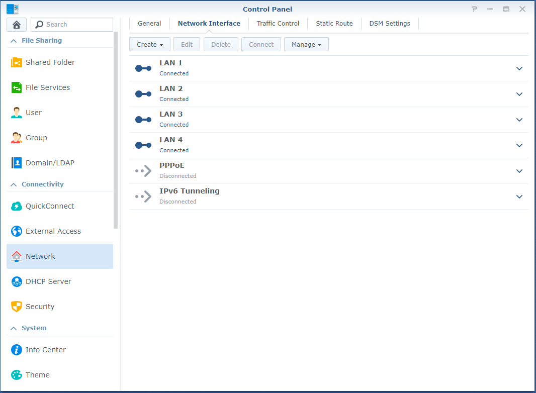
  1. First log in to the DSM web interface, and configure your NIC adapters in the Control Panel. As mentioned above, only configure the default gateway on one of your adapters.Synology Multiple NICs Configured Screenshot
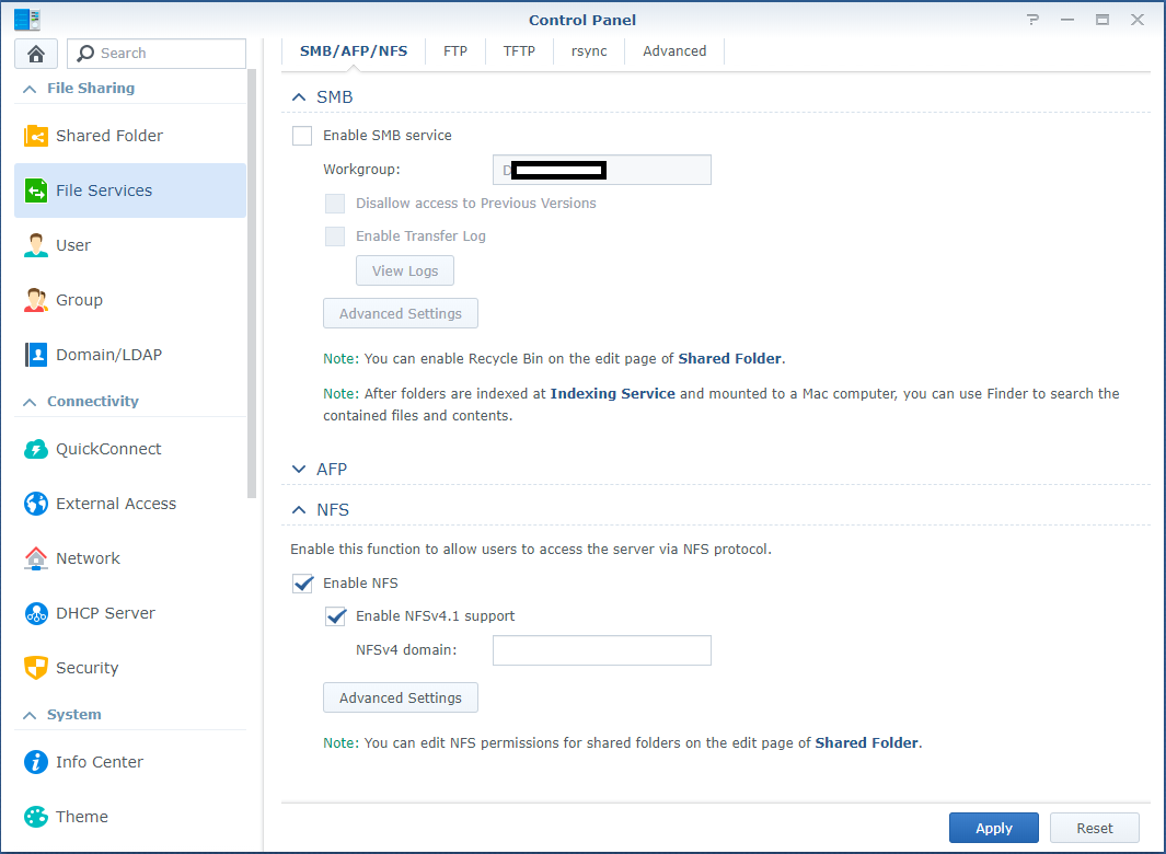
  2. While still in the Control Panel, navigate to “File Services” on the left, expand NFS, and check both “Enable NFS” and “Enable NFSv4.1 support”. You can leave the NFSv4 domain blank.Enabling NFSv4.1 on Synology DSM
  3. If you haven’t already configured an NFS export on the NAS, do so now. No further special configuration for v4.1 is required other than the norm.
  4. Log on to your ESXi host, go to storage, and add a new datastore. Choose to add an NFS datastore.
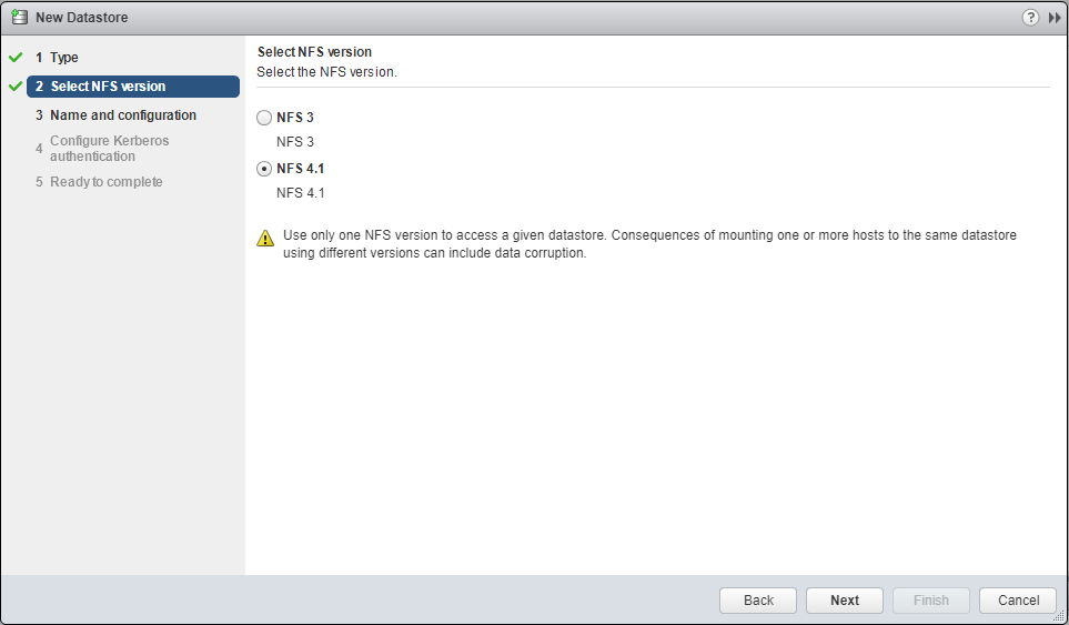
  5. On the “Select NFS version”, select “NFS 4.1”, and select next.Selecting the NFS version on the Add Datastore Dialog box on ESXi
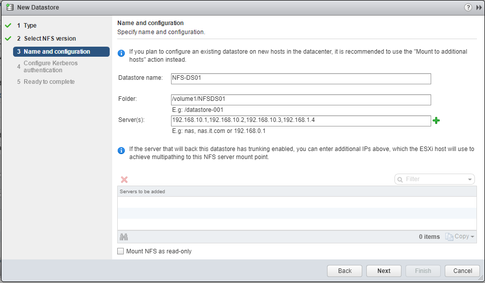
  6. Enter the datastore name, the folder on the NAS, and enter the Synology NAS IP addresses, separated by commas. Example below:New NFS Datastore details and configuration on ESXi dialog box
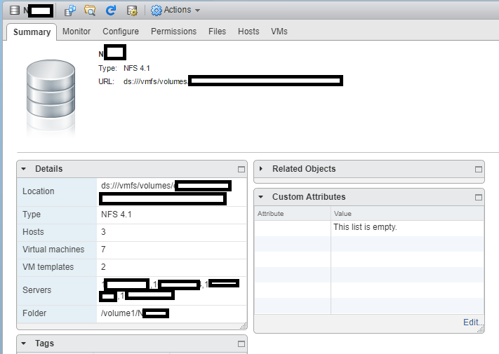
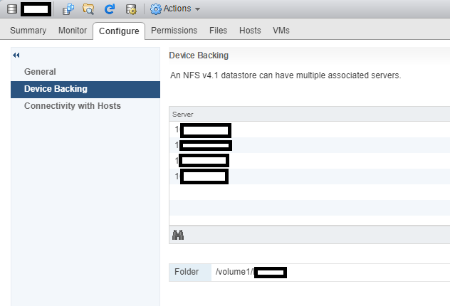
  7. Press the Green “+” and you’ll see it spreads them to the “Servers to be added”, each server entry reflecting an IP on the NAS. (please note I made a typo on one of the IPs).List of Servers/IPs for NFS Multipathing on ESXi Add Datastore dialog box
  8. Follow through with the wizard, and it will be added as a datastore.

That’s it! You’re done and are now using NFS Multipathing on your ESXi host!

In my case, I have all 4 NICs in my DS1813+ configured and connected to a switch. My ESXi hosts have 10Gb DAC connections to that switch, and can now utilize it at faster speeds. During intensive I/O loads, I’ve seen the full aggregated network throughput hit and sustain around 370MB/s.

After resolving the issues mentioned below, I’ve been running for weeks with absolutely no problems, and I’m enjoying the increased speed to the NAS.

Additional Important Information

After enabling this, I noticed that RAM and Memory usage had drastically increased on the Synology NAS. This would peak when my ESXi hosts would restart. This issue escalated to the NAS running out of memory (both physical and swap) and ultimately crashing.

After weeks of troubleshooting I found the processes that were causing this. While the processes were unrelated, this issue would only occur when using NFS Multipathing and NFS v4.1. To resolve this, I had to remove the “pkgctl-SynoFinder” package, and disable the services. I could do this in my environment because I only use the NAS for NFS and iSCSI. This resolved the issue. I created a blog post here to outline how to resolve this. I also further optimized the NAS and memory usage by disabling other unneeded services in a post here, targeted for other users like myself, who only use it for NFS/iSCSI.

Leave a comment and let me know if this post helped!