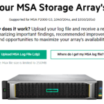
Are you having issues your HPE MSA SAN? Want to have more insight in to your storage array? Last week, HPE made available a new tool that allows you to check the health of your HPE MSA Storage Array!
While this tool was released to the public last week, rumor has it that this is the same tool that HPE uses internally when providing support to customers.
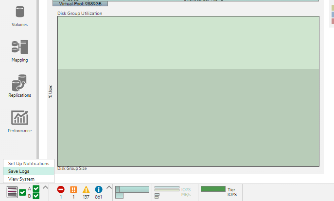
Log on to your MSA Array SMU (Storage Management Utility)
On the bottom left of the UI, click on the following up-arrow and select save logs
Wait for the logs to generate.
Download the logs to your computer
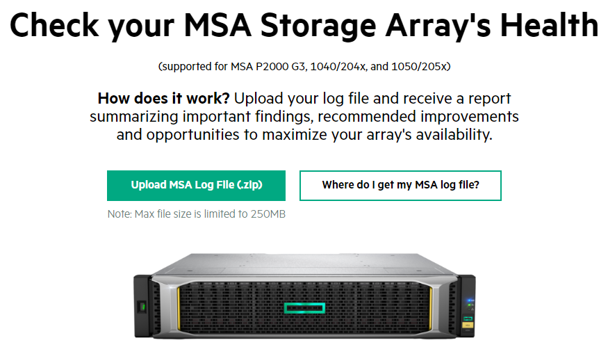
Open the MSA Storage Array Health Check
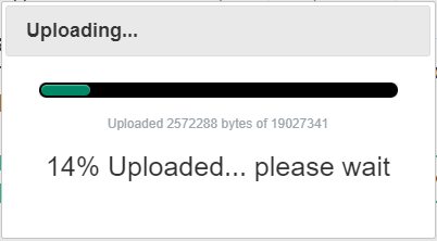
Click on the “Upload MSA Log File (.zip)” button, and then select your log dump zip file
Wait for the File to upload
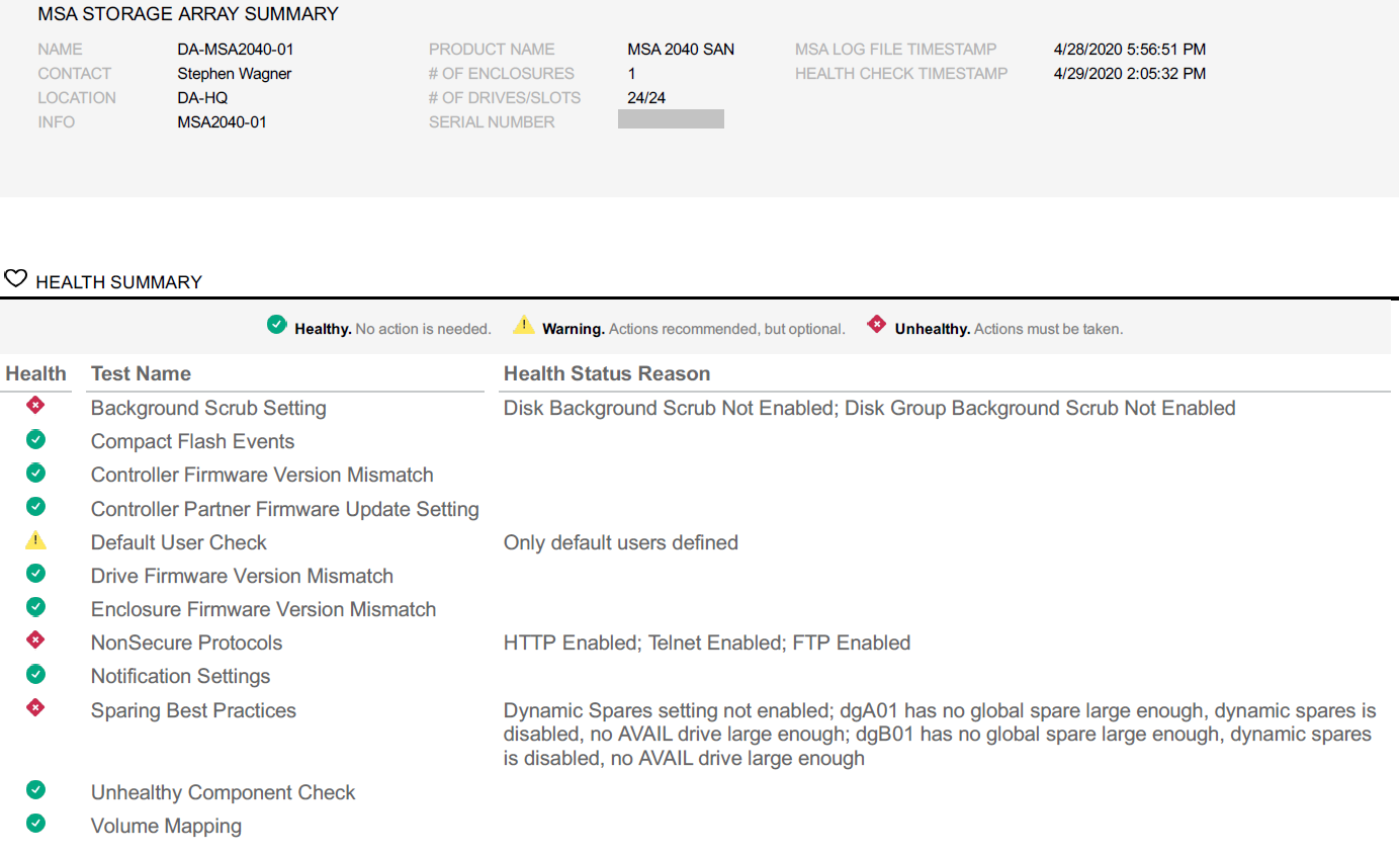
View your health report, and optionally download a PDF copy
And that’s it!
Available Tests
When running a health check, the following tests and checks are made on the log files:
Background Scrub Setting
Compact Flash Events
Controller Firmware Version Mismatch
Controller Partner Firmware Update Setting
Default User Check
Drive Firmware Version Mismatch
Enclosure Firmware Version Mismatch
NonSecure Protocols
Notification Settings
Sparing Best Practices
Unhealthy Component Check
Volume Mapping
Conclusion
Even if your MSA array is healthy, I’d still recommend generating a log dump and loading it up in to the MSA Health Check. Any extra visibility, is good visibility!
You may encounter a situation where you’re unable to connect to the management interface or NIC on your HPE MSA array. When this condition occurs, you are not able to ping the NIC, and the SMU (web interface) will not load.
When you visibly look at the array, the AMBER warning light may or may not be flashing.
If you have a dual controller setup, and connect to the SMU on the other controller, you may see numerous log entries where the management NIC port status changes repeatedly from up to down.
What’s happening
I’ve witnessed this issue occur on 2 separate HPE MSA 2040 storage arrays (both with dual controllers).
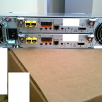
When you physically look at the management NICs on the controller in question, you’ll notice that the port status LED indicator turns on, and turns off repeatedly. The link status keeps changing from up to down (as reflected in the logs).
The Fix
Restarting the unit will have no effect. Changing the network cable will have no effect.
To resolve this issue, you must play with the network cable and re-seat it a few times (possibly half-way if possible a couple times as sketchy as that sounds).
If you can get the link status up, and disconnect/reconnect the cable before the light turns off, the connection will stay up. It will continue to function and survive restarts until sometime in the future when you disconnect it and reconnect it.
Replacing the controller may also fix it, however in the first instance I observed this, the replacement controller exhibited the same behavior months later in the future.
This weekend I came across a big issue with my HPE MSA 2040 where one of the SAN controllers became unresponsive, and appeared to had failed because it would not boot.
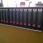
It all started when I decided to clean the MSA SAN. I try to clean the components once or twice a year to remove dust and make sure it’s not getting all jammed up. Sometimes I’ll shut the entire unit down and remove the individual components, other times I’ll remove them while operating. Because of the redundancies and since I have two controllers, I can remove and clean each controller individually at separate times.
Please Note: When dusting equipment with fans, never allow the fans to spin up with compressed air as this can generate current which can damage components. Never allow compressed air flow to spin up fans.
After cleaning out the power supplies, it came time to clean the controllers.
The Problem
As always, I logged in to the SMU to shutdown controller A (storage). I shut it down, the blue LED illuminated it was safe for removal. I then proceeded to remove it, clean it, and re-insert it. The controller came back online, and ownership of the applicable disk groups were successfully moved back. Controller A was now completed successfully. I continued to do the same for controller B: I logged in to shutdown controller B (storage). It shut down just like controller A, the blue LED removable light illuminated. I was able to remove it, clean it, and re-insert it.
However, controller B did not come back online.
After inserting controller B, the status light was flashing (as if it was booting). I waited 20 minutes with no change. The SMU on controller B was responding to HTTPS requests, however you could not log on due to the error “system is initializing”. SSH was functioning and you could log in and issue commands, however any command to get information would return “Please wait while this information is pulled from the MC controller”, and ultimately fail. The SMU on controller A would report a controller fault on controller B, and not provide any other information (including port status on controller B).
I then tried to re-seat the controller with the array still running. Gave it plenty of time with no effect.
I then removed the failed controller, shutdown the unit, powered it back on (only with controller A), and re-inserted Controller B. Again, no effect.
The Fix
At this point I’m thinking the controller may have failed or died during the cleaning process. I was just about to call HPE support for a replacement until I noticed the “Power LED” light inside of the failed controller would flash every 5 seconds while removed.
This made me start to wonder if there was an issue writing the cache to the compact flash card, or if the controller was still running off battery power but had completely frozen.
I tried these 3 things on the failed controller while it was unplugged and removed:
I left the controller untouched for 1 hour out of the array (to maybe let it finish whatever it was doing while on battery power)
There’s an unlabeled button on the back of the controller. As a last resort (thinking it was a reset button), I pressed and held it for 20 seconds, waited a minute, then briefly pressed it for 1 second while it was out of the unit.
I removed the Compact Flash card from the controller for 1 minute, then re-inserted it. In hoping this would fail the cache copy if it was stuck in the process of writing cache to compact flash.
I then re-inserted the controller, and it booted fine! It was not functioning and working (and came up very fast). Looking at the logs, it has no record of what occurred between the first shutdown, and final boot. I hope this post helps someone else with the same issue, it can save you a support ticket, and time with a controller down.
Disclaimer
PLEASE NOTE: I could not find any information on the unlabeled button on the controller, and it’s hard to know exactly what it does. Perform this at your own risk (make sure you have a backup). Since I have 2 controllers, and my MSA 2040 was running fine on Controller A, I felt comfortable doing this, as if this did reset controller B, the configuration would replicate back from controller A. I would not do this in a single controller environment.
Update – 24 Hours later
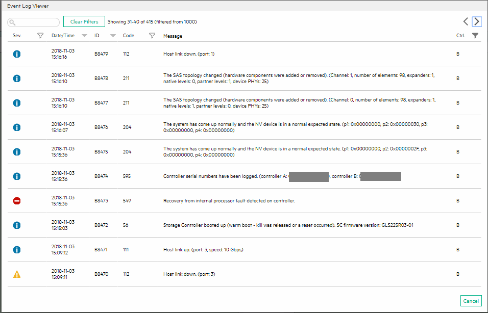
After I got everything up and running, I checked the logs of the unit and couldn’t find anything on controller B that looked out of ordinary. However, 24 hours later, I logged back in and noticed some new events showed up from the day before (from the day I had the issues):
MSA 2040 Code 549
You’ll notice the event log with severity error:
Recovery from internal processor fault detected on controller.
Code 549
One thing that’s very odd is that I know for a fact the time is wrong on the error severity log entry, this could be due to the fact we had a daylight savings time change last night at midnight. Either way it appears that it finally did detect that the Storage controller was in an error state and logged it, but it still would have been nice for some more information.
On a final note, the unit has been running perfectly for over 24 hours.
Update – April 2nd 2019
Well, in March a new firmware update was released for the MSA. I went to upgrade and the same issue as above occurred. During the firmware upgrade, at one point of the firmware update process a step had failed and repeated 4 times until successful.
During the Storage Controller restarting process, the controller never came back up. I removed the controller 1 hour, re-inserted and the above fix did not work. I then tried it after 2 hours of disconnection.
At this point I contacted HPE, who is sending a replacement controller.
The following day (12 hours of controller removed), I re-inserted it again and it actually booted up, was working with the new firmware, and then did a PFU (Partner Firmware Update) of controller A.
While it is working now, I’m still going to replace the controller as I believe something is not functioning correctly.
So, what happens in a worst-case scenario where your backup system fails, you don’t have any VM snapshots, and the last thing standing in the way of complete data loss is your SAN storage systems LUN snapshots?
Well, first you fire whoever purchased and implemented the backup system, then secondly you need to start restoring the VM (or VMs) from your SAN LUN snapshots.
While I’ve never had to do this in the past (all the disaster recovery solutions I’ve designed and sold have been tested and function), I’ve always been curious what the process is and would be like. Today I decided to try it out and develop a procedure for restoring a VM from SAN Storage LUN snapshot.
For this test I pretended a VM was corrupt on my VMware vSphere cluster and then restored it to a previous state from a LUN snapshot on my HPE MSA 2040 (identical for the HPE MSA 2050, and MSA 2052) Dual Controller SAN.
To accomplish the restore, we’ll need to create a host mapping on the SAN for the LUN snapshot to a new LUN number available to the hosts. We then need to add and mount the VMFS volume (residing on the snapshot) to the host(s) while assigning it a new signature and then vMotion the VM from the snapshot’s VMFS to original datastore.
Important Notes (Read first):
When mounting a VMFS volume from a SAN snapshot, you MUST RE-SIGNATURE THE SNAPSHOT VMFS volume. Not doing so can cause problems.
The snapshot cannot be mapped as read only, VMFS volumes must be marked as writable in order to be mounted on ESXi hosts.
You must follow the proper procedure to gracefully dismount and detach the VMFS volume and storage device before removing the snapshot’s host mapping on the SAN.
We use Storage vMotion to perform a high-speed move and recovery of the VM. If you’re not licensed for Storage vMotion, you can use the datastore file browser and copy/move from the snapshot VMFS volume to live production VMFS volume, however this may be slower.
During this entire process you do not touch, modify, or change any settings on your existing active production LUNs (or LUN numbers).
Restoring a VM from a SAN LUN snapshot will restore a crash consistent copy of the VM. The VM when recovered will believe a system crash occurred and power was lost. This is NOT a graceful application consistent backup and restore.
Please read your SAN documentation for the procedure to access SAN snapshots, and create host mappings. With the MSA 2040 I can do this live during production, however your SAN may be different and your hosts may need to be powered off and disconnected while SAN configuration changes are made.
Pro tip: You can also power on and initialize the VM from the snapshot before initiating the storage vMotion. This will allow you to get production services back online while you’re moving the VM from the snapshot to production VMFS volumes.
I’m not responsible if you damage, corrupt, or cause any damage or issues to your environment if you follow these procedures.
We are assuming that you have already either deleted the damaged VM, or removed it from your inventory and renamed the VMs folder on the live VMFS datastore to change the name (example, renaming the folder from “SRV01” to “SRV01.bad”. If you renamed the damaged VM, make sure you have enough space for the new restored VM as well.
Procedure:
Mount the VMFS volume on the LUN snapshot to the ESXi host(s)
Identify the VM you want to recover, write it down.
Identify the datastore that the VM resides on, write it down.
Identify the SAN and identify the LUN number that the VMFS datastore resides on, write it down.
Identify the LUN Snapshot unique name/id/number and write it down, confirm the timestamp to make sure it will contain a valid recovery point.
Log on to the SAN and create a host mapping to present the snapshot (you recorded above) to the hosts using a new and unused LUN number.
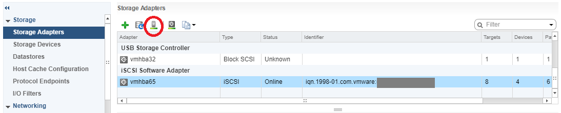
Log on to your ESXi host and navigate to configuration, then storage adapters.
Select the iSCSI initator and click the “Rescan Storage Adapters” button to rescan all iSCSI LUNs.
VMware ESXi Host Rescan Storage Adapter
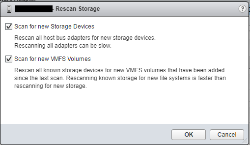
Ensure both check boxes are checked and hit “Ok”, wait for the scan to complete (as shown in the “Recent Tasks” window.
VMware ESXi Host Rescan Storage Adapter Window for VMFS Volume and Devices
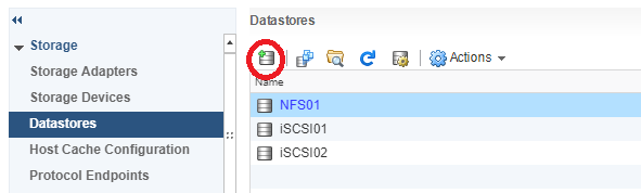
Now navigate to the “Datastores” tab under configuration, and click on the “Create a new Datastore” button as shown below.
VMware ESXi Host Add Datastore Window
Continue with “VMFS” selected and select continue.
In the next window, you’ll see your existing datastores, as well as your new datastore (from the snapshot). You can leave the “Datastore name” as is since this value will be ignored. In this window you’re going to select the new VMFS datastore from the snapshot. Make sure you confirm this by looking at the LUN number, as well as the value under “SnapshotVolume”. It is critical that you select the snapshot in this window (it should be the new LUN number you added above).
Select next and continue.
On the next window “Mount Option”, you need to change the radio button to and select “Assign a new signature”. This is critical! This will assign a new signature to differentiate it from your existing real production datastore so that the ESXi hosts don’t confuse it.
Continue with the wizard and complete the mount process. At this point ESXi will resignture the VMFS volume and rename it to “snap-OriginalVolumeNameHere”.
You can now browse the VMFS datastore residing on the LUN snapshot and do anything you’d normally be able to do with a normal datastore.
Copy/Move/vMotion the VM from the snapshot VMFS volume to your production VMFS volume
Note: The next steps are only if you are licensed for storage vMotion. If you aren’t you’ll need to use the copy or move function in the file browsing area to copy or move the VMs to your live production VMFS datastores:
Now we’ll go to the vCenter/ESXi host storage area in the web client, and using the “Files” tab, we’ll browse the snapshots VMFS datastore that we just mounted.
Locate the folder for the VM(s) you want to recover, open the folder, right click on the vmx file for the VM and select “Register VM”. Repeat this for any of the VMs you want to recover from the snapshot. Complete the wizard for each VM you register and add it to a host.
Go back to you “Hosts and VMs” view, you’ll now see the VMs are added.
Select and right click on the VM you want to move from the snapshot datastore to your production live datastore, and select “Migrate”.
In the vMotion migrate wizard, select “Change Storage only”.
Continue to the wizard, and storage vMotion the VM from the snapshot VMFS to your production VMFS volume. Wait for the vMotion to complete.
After the storage vMotion is complete, boot the VM and confirm everything is functioning.
Gracefully unmount, detach, and remove the snapshot VMFS from the ESXi host, and then remove the host mapping from the SAN
On each of your ESXi hosts that have access to the SAN, go to the “Datastores” section under the ESXi hosts configuration, right click on the snapshot VMFS datastore, and select “Unmount”. You’ll need to repeat this on each ESXi host that may have automounted the snapshot’s VMFS volume.
On each of your ESXi hosts that have access to the SAN, go to the “Storage Devices” section under the ESXi hosts configuration and identify (by LUN number) the “disk” that is the snapshot LUN. Select and highlight the snapshot LUN disk, select “All Actions” and select “Detach”. Repeat this on each host.
Double check and confirm that the snapshot VMFS datastore (and disk object) have been unmounted and detached from each ESXi host.
You can now log in to your SAN and remove the host mapping for the snapshot-to-LUN. We will not longer present the snapshot LUN to any of the hosts.
Back to the ESXi hosts, navigate to “Storage Adapters”, select the “iSCSI Initiator Adapter”, and click the “Rescan Storage Adapters”. Repeat this for each ESXi host.
There’s a new and easier way to find the latest firmware for your HPE MSA SAN!
A new website setup by HPE allows you to find the latest firmware for your HPE MSA 2050/2052, MSA 1050, MSA 2040/2042/1040, and/or MSA P2000 G3. This site will include the last 3 generations of SANs in the MSA product line.
This website uses cookies to improve your experience. We'll assume you're ok with this, but you can opt-out if you wish.
Do you accept the use of cookies and accept our privacy policy? AcceptRejectCookie and Privacy Policy
Privacy & Cookies Policy
Privacy Overview
This website uses cookies to improve your experience while you navigate through the website. Out of these cookies, the cookies that are categorized as necessary are stored on your browser as they are essential for the working of basic functionalities of the website. We also use third-party cookies that help us analyze and understand how you use this website. These cookies will be stored in your browser only with your consent. You also have the option to opt-out of these cookies. But opting out of some of these cookies may have an effect on your browsing experience.