Jun 072014
 

I’ve had the HPE MSA 2040 setup, configured, and running for about a week now. Thankfully this weekend I had some time to hit some benchmarks. Let’s take a look at the HPE MSA 2040 benchmarks on read, write, and IOPS.

First some info on the setup:

-2 X HPE Proliant DL360p Gen8 Servers (2 X 10 Core processors each, 128GB RAM each)

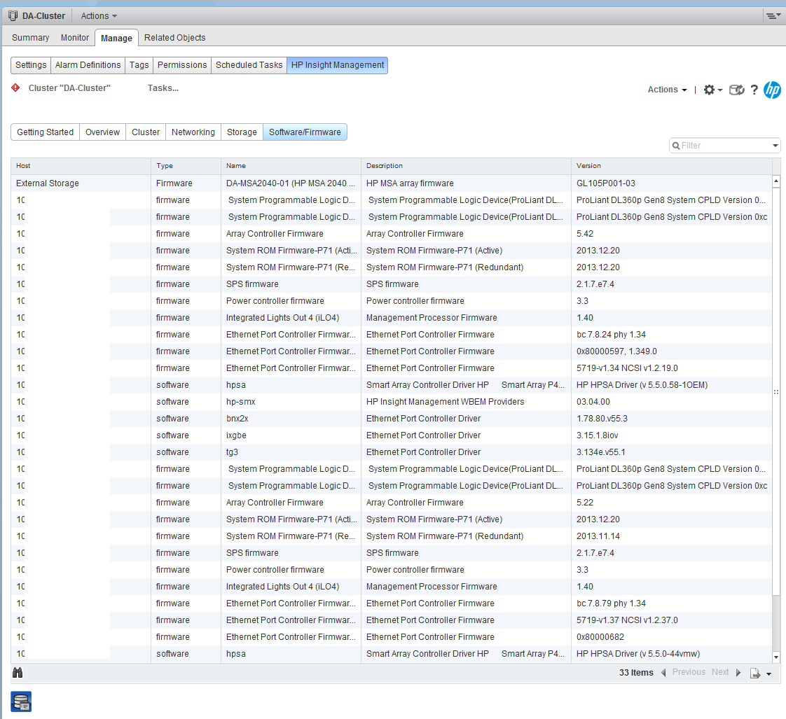
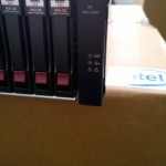
-HPE MSA 2040 Dual Controller – Configured for iSCSI

-HPE MSA 2040 is equipped with 24 X 900GB SAS Dual Port Enterprise Drives

-Each host is directly attached via 2 X 10Gb DAC cables (Each server has 1 DAC cable going to controller A, and Each server has 1 DAC cable going to controller B)

-2 vDisks are configured, each owned by a separate controller

-Disks 1-12 configured as RAID 5 owned by Controller A (512K Chunk Size Set)

-Disks 13-24 configured as RAID 5 owned by Controller B (512K Chunk Size Set)

-While round robin is configured, only one optimized path exists (only one path is being used) for each host to the datastore I tested

-Utilized “VMWare I/O Analyzer” (https://labs.vmware.com/flings/io-analyzer) which uses IOMeter for testing

-Running 2 “VMWare I/O Analyzer” VMs as worker processes. Both workers are testing at the same time, testing the same datastore.

Sequential Read Speed:

MSA2040-Read
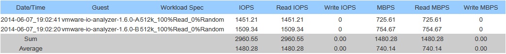
Max Read: 1480.28MB/sec

Sequential Write Speed:

MSA2040-Write
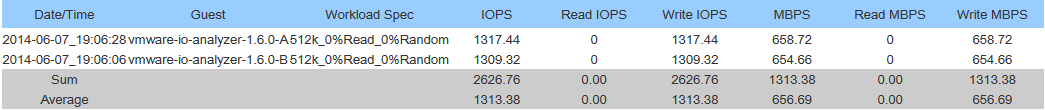
Max Write: 1313.38MB/sec

See below for IOPS (Max Throughput) testing:

Please note: The MaxIOPS and MaxWriteIOPS workloads were used. These workloads don’t have any randomness, so I’m assuming the cache module answered all the I/O requests, however I could be wrong. Tests were run for 120 seconds. What this means is that this is more of a test of what the controller is capable of handling itself over a single 10Gb link from the controller to the host.

IOPS Read Testing:

MSA2040-MaxIOPS
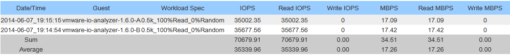
Max Read IOPS: 70679.91IOPS

IOPS Write Testing:

MSA2040-WriteOPS
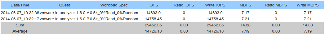
Max Write IOPS: 29452.35IOPS

PLEASE NOTE:

-These benchmarks were done by 2 seperate worker processes (1 running on each ESXi host) accessing the same datastore.

-I was running a VMWare vDP replication in the background (My bad, I know…).

-Sum is combined throughput of both hosts, Average is per host throughput.

Conclusion:

Holy crap this is fast! I’m betting the speed limit I’m hitting is the 10Gb interface. I need to get some more paths setup to the SAN!

Cheers

Jun 072014
 
vSphere Logo Image

Over the years I’ve come across numerous posts, blogs, articles, and howto guides that provide information on when to use iSCSI port binding, and they’ve all been wrong! Here, I’ll explain when to use iSCSI Port Binding, and why!

This post and information applies to all versions of VMware vSphere including 5, 5.5, 6, 6.5, 6.7, and 7.0.

See below for a video version of the blog post:

VMWare vSphere iSCSI Port Binding – When to use iSCSI Port Binding, and why!

What does iSCSI port binding do

iSCSI port binding binds a software iSCSI initiator interface on a ESXi host to a physical vmknic and configures it accordingly to allow multi-pathing (MPIO) in a situation where both vmknics are residing in the same subnet.

In normal circumstances without port binding, if you have multiple vmkernels on the same subnet (mulithomed), the ESXi host would simply choose one and not use both for transmission of packets, traffic, and data. iSCSI port binding forces the iSCSI initiator to use that adapter for both transmission and receiving of iSCSI packets.

In most simple SAN environments, there are two different types of setups/configurations.

  1. Multiple Subnet – Numerous paths to a storage device on a SAN, each path residing on separate subnets. These paths are isolated from each other and usually involve multiple switches.
  2. Single Subnet – Numerous paths to a storage device on a SAN, each path is on the same subnet. These paths usually go through 1-2 switches, with all interfaces on the SAN and the hosts residing on the same subnet.

IT professionals should be aware of the the issues that occur when you have a host that is multi-homed with multiple NICs on the same subnet.

In a normal typical scenario with Windows and Linux, if you have multiple adapters residing on the same subnet you’ll have issues with broadcasts and transmission of packets, and in most cases you have absolutely no control over what communications are initiated over what NIC due to the way the routing table is handled. In most cases all outbound connections will be initiated through the first NIC installed in the system, or whichever one is inside of the primary route in the routing table.

When to use iSCSI port binding

This is where iSCSI Port Binding comes in to play. If you have an ESXi host that has multiple vmk adapters sitting on the same subnet, you can bind the software iSCSI initiators (vmk adapters) to the physical NICs (vmnics). This allows multiple iSCSI connections on multiple NICs residing on the same subnet to transmit and handle the traffic properly.

So the general rule of thumb is:

  • One subnet, iSCSI port binding is the way to go!
  • Two or more subnets (multiple subnets), do not use iSCSI Port Binding! It’s just not needed since all vmknics are residing on different subnets.

Additional Information

Here’s two links to VMWare documentation explaining this in more detail:

For more information on configuring a vSphere Distributed Switch for iSCSI MPIO, click here!

And a final troubleshooting note: If you configure iSCSI Port Binding and notice that one of your interfaces is showing as “Not Used” and the other as “Last Used”, this is most likely due to either a physical cabling/switching issue (where one of the bound interfaces can’t connect to the iSCSI target), or you haven’t configured permissions on your SAN to allow a connection from that IP address.

Jun 072014
 
vSphere Logo Image

When I first started really getting in to multipath iSCSI for vSphere, I had two major hurdles that really took a lot of time and research to figure out before deploying.

  1. How to configure a vSphere Distributed Switch for iSCSI multipath MPIO with each path being on different subnets (a.k.a. each interface on separate subnets)
  2. Whether or not I should use iSCSI Port Binding

So many articles on the internet, and most were wrong.

In this article I’ll be getting in to the first point, how to configure a vSphere Distributed Switch for iSCSI multipath MPIO with multiple subnets. You can find information on the second point here, when to use iSCSI Port Binding, and why.

I’ll start off by saying that when using multiple subnets on multiple isolated networks for SAN connectivity, you DO NOT use iSCSI Port Binding.

Configure the vSphere Distirbuted Switch (vDS) for iSCSI MPIO

Configuring a standard (non distributed) vSphere Standard Switch is easy, but we want to do this right, right? By configuring a vSphere Distributed Switch, it allows you to roll it out to multiple hosts making configuration and provisioning more easy. It also allows you to more easily manage and maintain the configuration as well. In my opinion, in a fully vSphere rollout, there’s no reason to use vSphere Standard switches. Everything should be distributed!

The setup

My configuration consists of two hosts connecting to an iSCSI device over 3 different paths, each with it’s own subnet. Each host has multiple NICs, and the storage device has multiple NICs as well.

As always, I plan the deployment on paper before touching anything. When getting ready for deployment, you should write down:

  • Which subnets you will use
  • Choose IP addresses for your SAN and hosts
  • I always draw a map that explains what’s connecting to what. When you start rolling this out, it’s good to have that image in your mind and on paper. If you lose track it helps to get back on track and avoid mistakes.

For this example, let’s assume that we have 3 connections (I know it’s an odd number):

Subnets to be used:

  • 10.0.1.X
  • 10.0.2.X
  • 10.0.3.X

SAN Device IP Assignment:

  • 10.0.1.1 (NIC 1)
  • 10.0.2.1 (NIC 2)
  • 10.0.3.1 (NIC 3)

Host 1 IP Assignment:

  • 10.0.1.2 (NIC 1)
  • 10.0.2.2 (NIC 2)
  • 10.0.3.2 (Nic 3)

Host 2 IP Assignment:

  • 10.0.1.3 (NIC 1)
  • 10.0.2.3 (NIC 2)
  • 10.0.3.3 (NIC 3)

So no we know where everything is going to sit, and it’s addresses. It’s now time to configure a vSphere Distributed Switch and roll it out to the hosts.

Instructions

Let’s begin!

  1. We’ll start off by going in to the vSphere client and creating a new vSphere Distributed Switch. You can name this switch whatever you want, I’ll use “iSCSI-vDS” for this example. Going through the wizard you can assign a name. Stop when you get to “Add Hosts and Physical Adapter”, on this page we will chose “Add Later”. Also, when it asks us to create a default port group, we will un-check the box and NOT create one.
  2. Now we need to create some “Port Groups”. Essentially we will be creating a Port Group for each subnet and NIC for the storage configuration. In this example case, we have 3 subnets, and 3 NICs per host, so we will be creating 3 port groups. Go ahead and right click on the new vSphere distributed switch we created (“iSCSI-vDS” in my example), and create a new port group. I’ll be naming my first one “iSCSI-01”, second will be called “iSCSI-02”, and so on. You can go ahead and create one for each subnet. After these are created, we’ll end up with this:
  3. After we have this setup, we now need to do some VERY important configuration. As of right now by default, each port group will have all uplinks configured as Active which we DO NOT want. Essentially what we will be doing, is assigning only one Active Uplink per Port Group. Each port group will be on it’s own subnet, so we need to make sure that the applicable uplink is only active, and the remainder are thrown in to the “Unused Uplinks” section. This can be achieved by right clicking on each port group, and going to “Teaming and Failover” underneath “Policies”. You’ll need to select the applicable uplinks and using the “Move Down” button, move them down to “Unused Uplinks”. Below you’ll see some screenshots from the iSCSI-02, and iSCSI-03 port groups we’ve created in this example:

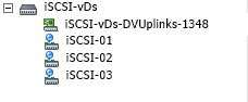
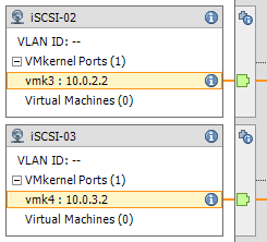
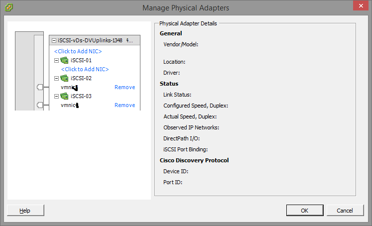
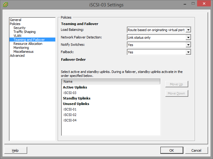
    You’ll notice that the iSCSI-02 port group, only has the iSCSI-02 uplink marked as active. Also, the iSCSI-03 port group, only have the iSCSI-03 uplink marked as active. The same applies to iSCSI-01, and any other links you have (more if you have more links). Please ignore the entry for “iSCSI-04”, I created this for something else, pretend the entry isn’t there. If you do have 4 subnets, and 4 NICs, then you would have a 4th port group.
  4. Now we need to add the vSphere Distributed Switches to the hosts. Right click on the “iSCSI-vDS” Distributed switch we created and select “Add Host”. Select ONLY the hosts, and DO NOT select any of the physical adapters. A box will appear mentioning you haven’t selected any physical adapters, simply hit “Yes” to “Do you want to continue adding the hosts”. For the rest of the wizard just keep hitting “Next”, we don’t need to change anything. Example below:

    So here we are now, we have a vSphere Distributed Switch created, we have the port groups created, we’ve configured the port groups, and the vDS is attached to our hosts… Now we need to create vmks (vmkernel interfaces) in each port group, and then attach physical adapters to the port groups.
  5. Head over to the Configuration tab inside of your ESXi host, and go to “Networking”. You’ll notice the newly created vSphere Distributed Switch is now inside the window. Expand it. You’ll need to perform these steps on each of your ESXi hosts. Essentially what we are doing, is creating a vmk on each port group, on each host. Click on “Manage Virtual Adapters” and click on “Add”. We’ll select “New Virtual Adapter”, then on the next screen our only option will be “VMKernel”, click Next. In the “Select port group” option, select the applicable port group. You’ll need to do this multiple times as we need to create a vmkernel interface for each port group (a vmk on iSCSI-01, a vmk on iSCSI-02, etc…), on each host, click next. Since this is the first port group (iSCSI-01) vmk we are creating on the first host, we’ll assign the IP address as 10.0.1.2, fill in the subnet box, and finish the wizard. Create another vmk for the second port group (iSCSI-02), since it’s the first host it’ll have an IP of 10.0.2.2, and then again for the 3rd port group with an IP of 10.0.3.2. After you do this for the first host, you’ll need to do it again for the second host, only the IPs will be different since it’s a different host (in this example the second host would have 3 vmks on each port group, example: iSCSI01 – 10.0.1.3, iSCSI02 – 10.0.2.3, iSCSI03 – 10.0.3.3). Here’s an example of iSCSI02 and iSCSI03 on ESXi host 1. Of course there’s also a iSCSI-01 but I cut it from the screenshot.
  6. Now we need to “manage the physical adapters” and attach the physical adapters to the individual port groups. Essentially this will map the physical NIC to the separate subnets port groups we’ve created for storage in the vDS. We’ll need to do this on both hosts. Inside of the “Managed Physical Adapters” box, you’ll see each port group on the left hand side, click on “<Click to Add NIC>”. Now in everyone’s environments the vmnic you add will be different. You should know what the physical adapter you want to map to the subnet/port group is. I’ve removed the vmnic number from the below screenshot just in case… And to make sure you think about this one…

As mentioned above, you need to do this on both hosts for the applicable vmnics. You’ll want to assign all 3 (even though I’ve only assigned 2 in the above screenshot).

Voiala! You’re done! Now all you need to do is go in to your iSCSI initiator and add the IPs of the iSCSI target to the dynamic discovery tab on each host. Rescan the adapter, add the VMFS datastores and you’re done.

If you have any questions or comments, or feel this can be done in a better way, drop a comment on this article. Happy Virtualizing!

Jumbo Frames

There is one additional step if you are using jumbo frames. Please note that to use jumbo frames, all NICs, physical switches, and the storage device itself need to be configured to support this. On the VMWare side of things, you need to apply the following settings:

  1. Under “Inventory” and “Networking”, Right Click on the newly created Distributed Switch. Under the “Properties” tab, select “Advanced” on the left hand side. Change the MTU to the applicable frame size. In my scenario this is 9000.
  2. Under “Inventory” and “Hosts and Clusters”, click on the “Configuration Tab”, then “vSphere Distributed Switch”. Expand the newly created “Distributed Switch”, select “Manage Virtual Adapters”. Select a vmk interface, and click “edit”. Change the MTU to the applicable size, in my case this is 9000. You’ll need to do this for each vmk interface on each physical host.

Good luck with your setup and configuration!

Jun 072014
 

So, you have:

2 X HP Proliant DL360p Gen8 Servers with 2 X 10 Core Processors

1 X MSA 2040 SAN – With Dual Controllers


And you want more visibility, functionality, and more important “Insight” on your systems where the hardware meets the software. This is where HP Insight Control for VMWare comes in to play.

This package is amazing for providing information and “Insight” in to all your equipment, including servers and storage units. It allows you to update firmware, monitor and manage servers, monitor and manage storage arrays, and rapidly deploy new data stores and manage existing ones. It makes all this information and functionality available via the vSphere management interfaces, which is just fantastic.


I was browsing the downloads area on HP’s website for the MSA 2040, and the website told me I should download “Insight Control for VMWare”, I figured why not! After getting this package installed, I instantly saw the value.

HP Insight control for VMWare, allows you to access server health, management, and control, along with storage health, management, and control. It supports HP servers with iLo, and fully supports the MSA 2040 SAN.

Installation was a breeze, it was installed within seconds. I chose to install it directly on to my demo vSphere 5.5 vCenter server. Barely any configuration is required, the installation process was actually a few clicks of “Next”. Once install, you simply have to configure iLo credentials, and then add your storage system if you have a compatible SAN. Even adding your SAN is super easy, and it allows you to choose whether you want Insight Control to have full access to the SAN (which allows you to create, and manage datastores), or only Read Only, which only allows it to pull information from the unit.


And for those of you concerned about port conflicts, it uses:

3500,3501, 3502, 3503, 3504, 3505, 3506, 3507, 3508, 3509, 3510, 3512, 3513, 3511, 8090.


The Insight Control for VMWare is available through both the software client, and the web client. As far as I’m concerned it’s a “must have” if your running HP equipment in your vSphere environment!

HP Insight Control Firmware Management Page

HP Insight Control Firmware Management Page

HP Insight Control for VMWare on Software Client for vSphere

HP Insight Control for VMWare on Software Client for vSphere

HP Insight Control for VMWare showing iSCSI initiator paths

HP Insight Control for VMWare showing iSCSI initiator paths

HP Insight Control for VMWare Web Client

HP Insight Control for VMWare Web Client

HP Inight Control for VMWare Overview in Web Client

HP Inight Control for VMWare Overview in Web Client