When I first started really getting in to multipath iSCSI for vSphere, I had two major hurdles that really took a lot of time and research to figure out before deploying.
- How to configure a vSphere Distributed Switch for iSCSI multipath MPIO with each path being on different subnets (a.k.a. each interface on separate subnets)
- Whether or not I should use iSCSI Port Binding
So many articles on the internet, and most were wrong.
In this article I’ll be getting in to the first point, how to configure a vSphere Distributed Switch for iSCSI multipath MPIO with multiple subnets. You can find information on the second point here, when to use iSCSI Port Binding, and why.
I’ll start off by saying that when using multiple subnets on multiple isolated networks for SAN connectivity, you DO NOT use iSCSI Port Binding.
Configure the vSphere Distirbuted Switch (vDS) for iSCSI MPIO
Configuring a standard (non distributed) vSphere Standard Switch is easy, but we want to do this right, right? By configuring a vSphere Distributed Switch, it allows you to roll it out to multiple hosts making configuration and provisioning more easy. It also allows you to more easily manage and maintain the configuration as well. In my opinion, in a fully vSphere rollout, there’s no reason to use vSphere Standard switches. Everything should be distributed!
The setup
My configuration consists of two hosts connecting to an iSCSI device over 3 different paths, each with it’s own subnet. Each host has multiple NICs, and the storage device has multiple NICs as well.
As always, I plan the deployment on paper before touching anything. When getting ready for deployment, you should write down:
- Which subnets you will use
- Choose IP addresses for your SAN and hosts
- I always draw a map that explains what’s connecting to what. When you start rolling this out, it’s good to have that image in your mind and on paper. If you lose track it helps to get back on track and avoid mistakes.
For this example, let’s assume that we have 3 connections (I know it’s an odd number):
Subnets to be used:
- 10.0.1.X
- 10.0.2.X
- 10.0.3.X
SAN Device IP Assignment:
- 10.0.1.1 (NIC 1)
- 10.0.2.1 (NIC 2)
- 10.0.3.1 (NIC 3)
Host 1 IP Assignment:
- 10.0.1.2 (NIC 1)
- 10.0.2.2 (NIC 2)
- 10.0.3.2 (Nic 3)
Host 2 IP Assignment:
- 10.0.1.3 (NIC 1)
- 10.0.2.3 (NIC 2)
- 10.0.3.3 (NIC 3)
So no we know where everything is going to sit, and it’s addresses. It’s now time to configure a vSphere Distributed Switch and roll it out to the hosts.
Instructions
Let’s begin!
- We’ll start off by going in to the vSphere client and creating a new vSphere Distributed Switch. You can name this switch whatever you want, I’ll use “iSCSI-vDS” for this example. Going through the wizard you can assign a name. Stop when you get to “Add Hosts and Physical Adapter”, on this page we will chose “Add Later”. Also, when it asks us to create a default port group, we will un-check the box and NOT create one.
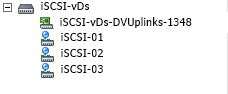
- Now we need to create some “Port Groups”. Essentially we will be creating a Port Group for each subnet and NIC for the storage configuration. In this example case, we have 3 subnets, and 3 NICs per host, so we will be creating 3 port groups. Go ahead and right click on the new vSphere distributed switch we created (“iSCSI-vDS” in my example), and create a new port group. I’ll be naming my first one “iSCSI-01”, second will be called “iSCSI-02”, and so on. You can go ahead and create one for each subnet. After these are created, we’ll end up with this:
- After we have this setup, we now need to do some VERY important configuration. As of right now by default, each port group will have all uplinks configured as Active which we DO NOT want. Essentially what we will be doing, is assigning only one Active Uplink per Port Group. Each port group will be on it’s own subnet, so we need to make sure that the applicable uplink is only active, and the remainder are thrown in to the “Unused Uplinks” section. This can be achieved by right clicking on each port group, and going to “Teaming and Failover” underneath “Policies”. You’ll need to select the applicable uplinks and using the “Move Down” button, move them down to “Unused Uplinks”. Below you’ll see some screenshots from the iSCSI-02, and iSCSI-03 port groups we’ve created in this example:

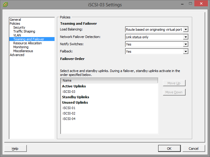 You’ll notice that the iSCSI-02 port group, only has the iSCSI-02 uplink marked as active. Also, the iSCSI-03 port group, only have the iSCSI-03 uplink marked as active. The same applies to iSCSI-01, and any other links you have (more if you have more links). Please ignore the entry for “iSCSI-04”, I created this for something else, pretend the entry isn’t there. If you do have 4 subnets, and 4 NICs, then you would have a 4th port group.
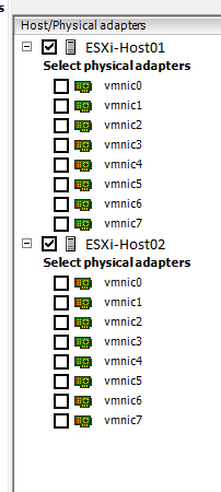
 - Now we need to add the vSphere Distributed Switches to the hosts. Right click on the “iSCSI-vDS” Distributed switch we created and select “Add Host”. Select ONLY the hosts, and DO NOT select any of the physical adapters. A box will appear mentioning you haven’t selected any physical adapters, simply hit “Yes” to “Do you want to continue adding the hosts”. For the rest of the wizard just keep hitting “Next”, we don’t need to change anything. Example below:
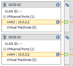
So here we are now, we have a vSphere Distributed Switch created, we have the port groups created, we’ve configured the port groups, and the vDS is attached to our hosts… Now we need to create vmks (vmkernel interfaces) in each port group, and then attach physical adapters to the port groups. - Head over to the Configuration tab inside of your ESXi host, and go to “Networking”. You’ll notice the newly created vSphere Distributed Switch is now inside the window. Expand it. You’ll need to perform these steps on each of your ESXi hosts. Essentially what we are doing, is creating a vmk on each port group, on each host. Click on “Manage Virtual Adapters” and click on “Add”. We’ll select “New Virtual Adapter”, then on the next screen our only option will be “VMKernel”, click Next. In the “Select port group” option, select the applicable port group. You’ll need to do this multiple times as we need to create a vmkernel interface for each port group (a vmk on iSCSI-01, a vmk on iSCSI-02, etc…), on each host, click next. Since this is the first port group (iSCSI-01) vmk we are creating on the first host, we’ll assign the IP address as 10.0.1.2, fill in the subnet box, and finish the wizard. Create another vmk for the second port group (iSCSI-02), since it’s the first host it’ll have an IP of 10.0.2.2, and then again for the 3rd port group with an IP of 10.0.3.2. After you do this for the first host, you’ll need to do it again for the second host, only the IPs will be different since it’s a different host (in this example the second host would have 3 vmks on each port group, example: iSCSI01 – 10.0.1.3, iSCSI02 – 10.0.2.3, iSCSI03 – 10.0.3.3). Here’s an example of iSCSI02 and iSCSI03 on ESXi host 1. Of course there’s also a iSCSI-01 but I cut it from the screenshot.
- Now we need to “manage the physical adapters” and attach the physical adapters to the individual port groups. Essentially this will map the physical NIC to the separate subnets port groups we’ve created for storage in the vDS. We’ll need to do this on both hosts. Inside of the “Managed Physical Adapters” box, you’ll see each port group on the left hand side, click on “<Click to Add NIC>”. Now in everyone’s environments the vmnic you add will be different. You should know what the physical adapter you want to map to the subnet/port group is. I’ve removed the vmnic number from the below screenshot just in case… And to make sure you think about this one…
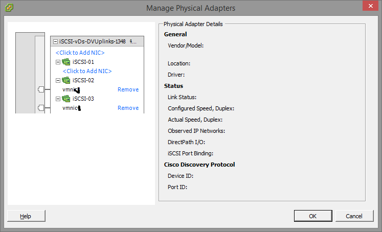
As mentioned above, you need to do this on both hosts for the applicable vmnics. You’ll want to assign all 3 (even though I’ve only assigned 2 in the above screenshot).
Voiala! You’re done! Now all you need to do is go in to your iSCSI initiator and add the IPs of the iSCSI target to the dynamic discovery tab on each host. Rescan the adapter, add the VMFS datastores and you’re done.
If you have any questions or comments, or feel this can be done in a better way, drop a comment on this article. Happy Virtualizing!
Jumbo Frames
There is one additional step if you are using jumbo frames. Please note that to use jumbo frames, all NICs, physical switches, and the storage device itself need to be configured to support this. On the VMWare side of things, you need to apply the following settings:
- Under “Inventory” and “Networking”, Right Click on the newly created Distributed Switch. Under the “Properties” tab, select “Advanced” on the left hand side. Change the MTU to the applicable frame size. In my scenario this is 9000.
- Under “Inventory” and “Hosts and Clusters”, click on the “Configuration Tab”, then “vSphere Distributed Switch”. Expand the newly created “Distributed Switch”, select “Manage Virtual Adapters”. Select a vmk interface, and click “edit”. Change the MTU to the applicable size, in my case this is 9000. You’ll need to do this for each vmk interface on each physical host.
Good luck with your setup and configuration!
I do not agree, read: https://adventuresinclouds.com/2016/10/24/vsphere-lab-for-beginners-part-4-virtual-distributed-switches-migrating-networking-vss-to-vds/
Hi fields1983,
The information in my post, and the information in the link in your post are for two separate scenarios.
Whoever uses either of the instructions need to use the post that’s relevant to their own configuration and scenario.
Thanks for contributing!
Cheers,
Stephen
[…] For more information on configuring a vSphere Distributed Switch for iSCSI MPIO, click here! […]
I see you use three vmkernel adaptor.
is there any limitation on vmkernel adaptor on software iscsi initiator?
Hey John,
I used 3 to make an example of 3 different networks (or physical paths) to the SAN in this example. The limitations on vmk’s for iSCSI would probably match the limitations for vmk’s in general.
Normally in most environments with high speed networking, they’ll have 2 redundant switches, with hosts that have anywhere from 2-4 uplinks per host. Sometimes you may have more if you are only using 1Gb networking, sometimes more for high speed as well.
Hope that helps!
Cheers,
Stephen
Slightly confused here because once you have created the dswitch you cannot then do anything with it on the individual ESXi hosts which your guide seems to be suggesting you can.
I have done it all on vcenter but am unclear on the last bit about mapping port groups to vmnics. On the individual hypervisor in the vswitch topology it shows both vmks but does not tie each vmk to a specific vmnic.
I assume they should be ?
Hi Jon,
If you’re using a vDS switch, the configuration is all done centrally when configuring the switch. After the configuration on the switch is done, you attach it to the hosts and then assign the uplinks.
After the vDS switch is configured, you assign it to the host and then configure (add) the uplinks (physical NICs).
Cheers,
Stephen