Mar 222020
 
Ubiquiti UniFi US-48 Switch, UniFi nanoHD Wireless AP, 2 x UF-RJ45-10G SFP+ Modules

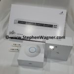
So you’ve purchased some Ubiquiti UniFi hardware… You have configured it, possibly even changed your management VLAN. Now it’s time to get production ready.

When you start getting in to complicated setups with VLANs, multiple subnets, etc… Planning your UniFi deployment can get tricky.

I’ve had numerous readers reach out after reading my Ubiquiti UniFi Review and ask questions about their UniFi adoption issues, as well as what the best method is.

I regularly see IT professionals adopting via SSH or the mobile app, however in best practice and large deployments you want this to be automated and require as little human intervention as possible.

All an IT administrator should have to do is connect the device to the network and see it in the UniFi Controller. This should apply to the most simplistic, as well as the most advanced deployments.

Design

If you’re using multiple subnets and multiple VLANs, you need to make sure that when a new UniFi device (such as an Access Point or Switch) is connected, that the following two things occur:

  1. It can get an IP address from a DHCP Server
  2. It can reach out to a UniFi controller (we’ll get in to this more in a bit)

In more complicated environments, your UniFi controller may be sitting on a different VLAN and you may also have your management VLAN on a different VLAN as well (where your UniFi devices reside after adoption).

My Environment

Screenshot of 1 UniFi Switch and 2 UniFi NanoHD's adopted in the UniFi Controller
UniFi Devices Adopted in the UniFi Controller

In my environment, the following is true:

  • No devices except a DHCP/DNS server and firewall/router sit on the untagged VLAN of 1.
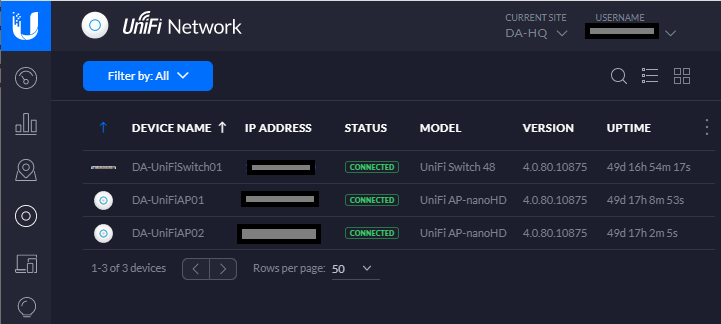
  • My UniFi devices (including controller, Access Points, and switches) have a separate dedicated management VLAN.

The purpose of having an untagged VLAN of 1 is to allow provisioning of devices that self or auto provision. This network is an isolated network that is heavily controlled via the router and firewall that is running IPS (Intrusion Prevention System) and strict firewall rules.

Normally I wouldn’t even have anything on the untagged VLAN of 1, however a provisioning network is needed. For example when you plug in a UniFi NanoHD, or a UniFi Switch, it’ll grab an IP on the untagged VLAN of 1, and look for a controller to present itself to for adoption.

Best Adoption Method

No matter how simple or complex the environment is I always recommend using the DNS method of adoption.

Most networks have DHCP and DNS, whether it’s for workstations, servers, or IT infrastructure. It’s extremely easy to setup a DNS Host (A) record or an Alias (CNAME) record of “unifi” and have it point to your UniFi Controller.

If you’re using multiple VLANs and subnets, your network must be fully routable from the untagged VLAN of 1, all the way to your UniFi controller.

I highly recommend putting strict firewall rules in place to only allow communication to the UniFi Controller from the untagged VLAN 1.

Conclusion

Following these practices allow you to simplify your UniFi deployment even on extremely large and complex networks, while not straying from keeping your network secure!

Everything is automated, efficient, and ready to use!

Leave a comment and leave me some feedback!

Mar 212020
 
CanaKit Raspberry Pi 4 Case with cables

During a previous project I needed to create a fresh and clean boot partition for a Raspberry Pi. I needed to create the partition layout required for the Raspberry Pi to see and boot a Linux kernel from.

There are many guides on the internet on how to write a Raspberry Pi image (which includes the system-boot partition), but I wanted a clean and fresh partition layout, without the additional partitions containing the Linux operating system.

I was creating a new Micro SD card with the purpose of using an NFS Root for the Raspberry Pi. For those of you that don’t know, you can boot a Raspberry Pi (or Linux computer) from local media, whether it’s a CD, USB Stick, Micro SD, or hard drive, and then have the actual operating system root file system be loaded via NFS. You can also use PXE to boot the kernel requiring no local storage, but that’s beyond the scope of this article.

Raspberry Pi default Partition layout

Below, we’ll look at the default partition layout you’d see on a Raspberry Pi using a prebuild linux image.

Disk /dev/sda: 59.6 GiB, 64021856256 bytes, 125042688 sectors
Units: sectors of 1 * 512 = 512 bytes
Sector size (logical/physical): 512 bytes / 512 bytes
I/O size (minimum/optimal): 512 bytes / 512 bytes
Disklabel type: dos
Disk identifier: 0x97709164
Device     Boot  Start       End   Sectors  Size Id Type
/dev/sda1         8192    532479    524288  256M  c W95 FAT32 (LBA)
/dev/sda2       532480 125042687 124510208 59.4G 83 Linux

I’m using a USB to Micro SD adapter to view the partitions on this card, so it’s being presented to the system as “/dev/sda”. On a normal computer “/dev/sda” is the first hard drive (usually the OS) so be careful when using these commands.

You’ll notice that “/dev/sda1” is the Raspberry Pi boot partition, with an Id of 3, and has the type of “W95 FAT32 (LBA)”.

The second partition which is the filesystem root (which I moved to NFS), is “/dev/sda2”, with an Id of 83, and has a type of “Linux”.

Creating a fresh partition layout with only the boot partition

In this guide we’re going to setup a Micro SD card with a fresh boot partition for the Raspberry Pi from scratch. We are not using an image and we are not using the expansion feature.

We’re going to assume that your destination SD card is empty. If it isn’t, you’ll need to delete all the partitions using “fdisk /dev/device”, and then deleted them with “d”.

Alternatively, to delete existing partition information you can wipe the MBR and partition table with the following command. Replace “/dev/device” with the actual device label for the card. Note that this will render existing data useless and unrecoverable.

dd if=/dev/zero of=/dev/DEVICE bs=512 count=1

Please Note: Make sure you are running this command on the right device. Afterwards, unplug and re-insert the SD card.

Creating the layout

On an empty Micro SD card:

  1. Open fdisk on your card.
    fdisk /dev/sda
  2. Press “n” to create a partition.
  3. Press “p” to make it a primary partition.
  4. Press “1” to make it the first partition in the table.
  5. Press <enter> to accept the default on start sector.
  6. Type +size to choose the size. In my case I want 1GB, so I’ll type “+1G”.
  7. After it’s created, press “a” to make it bootable.
  8. Now we press “p” to print and view the partition table, as shown below.
    Command (m for help): p
    Disk /dev/sda: 3.7 GiB, 3965190144 bytes, 7744512 sectors
    Geometry: 122 heads, 62 sectors/track, 1023 cylinders
    Units: sectors of 1 * 512 = 512 bytes
    Sector size (logical/physical): 512 bytes / 512 bytes
    I/O size (minimum/optimal): 512 bytes / 512 bytes
    Disklabel type: dos
    Disk identifier: 0x4eb27b84
    Device Boot Start End Sectors Size Id Type
    /dev/sda1 * 2048 2099199 2097152 1G 83 Linux
  9. Now we need to set the partition type. Press “t” to set a partition type, choose the partition, and type “c” for “W95 FAT32 (LBA)”.
  10. We’re now left with this partition table.
    Image of a new clean Raspberry Pi Boot Partition Layout
  11. Press “w” to write and save, and exit fdisk.
  12. We now need to format the partition. Run the following command on your device.
    mkfs.vfat /dev/sda1

Finally, you can now set a label to the partition. Ubuntu uses the label “system-boot” whereas Raspbian uses “boot”. You can set it with the following command:

fatlabel /dev/device NEW_LABEL

You now have a clean partition layout that can be used to boot a Raspberry Pi. Remember that this is just the partition layout and the files are still needed from an image or your current running instance. These can simply be copied over.

In my case, I just mounted an old and the new partitions to directories and copied the data over. This allowed me to modify the new boot partition and ultimately make it boot in to an NFS root.

If you need just a simple boot partition, you don’t need to purchase large Micro SD cards.

Mar 212020
 
CanaKit Raspberry Pi 4 case open with Fan Kit and running

In this post you’ll find a list of handy tips, tricks, and commands for your new Raspberry Pi 4.

I’ve been maintaining a document to record these so I can search and re-use them, and figured I’d share them on the blog for others to use as well.

I’m hoping to target both Raspbian and Ubuntu Server for the Raspberry Pi 4. If you have any feedback or input, please leave a comment!

Enable 64-Bit Kernel on Raspbian

Enables 64-bit kernel on Raspbian, however remember that the userspace is still 32-bit.

  1. Run “rpi-update” to make sure you’re running latest firmware and kernel.
    rpi-update
  2. Add “arm_64bit=1” to “/boot/config.txt”
    sudo echo arm_64bit=1 >> /boot/config.txt
  3. Restart

Remove, comment out, or set the value to 0 to go back to a 32-bit kernel.

Get CPU Temperature on Raspbian

Run the command “sudo vcgencmd measure_temp” to get the CPU temperature on Raspbian.

pi@raspberrypi:~ $ sudo vcgencmd measure_temp
temp=38.0'C

Get CPU Temperature on Ubuntu Server

Run the command “paste <(cat /sys/class/thermal/thermal_zone/type) <(cat /sys/class/thermal/thermal_zone/temp) | column -s $’\t’ -t | sed ‘s/(.)..$/.\1°C/'” as root to get the CPU temperature on Ubuntu Server.

root@ubuntu:~# paste <(cat /sys/class/thermal/thermal_zone/type) <(cat /sys/class/thermal/thermal_zone/temp) | column -s $'\t' -t | sed 's/(.)..$/.\1°C/'
cpu-thermal  45.2°C

Add root CA (Certification Authority) certificates to the trust on Raspbian and Ubuntu Server

To add a root CA to your CA trust on your Linux instance, perform the following:

  1. Save your certificate as a friendly-filename.crt (CRT extension is important) and copy to “/usr/local/share/ca-certificates/”.
  2. Run the “update-ca-certificates” command as root or sudo.
    update-ca-certificates

Install Cockpit Remote Web Administration

To install cockpit on your Raspberry Pi, run the following command as root or sudo:

apt install cockpit

After this, login to Cockpit on your Pi by pointring your browser to https://PI-IP-ADDRESS:9090

To install the Target CLI to configure the iSCSI Target

In order to configure the Linux kernel iSCSI target, you need the “targetcli” application/binary.

To install on Raspbian, run the command as root or sudo:

apt install targetcli

To install on Ubuntu Server, run the command as root or sudo:

apt install targetcli-fb

Mar 192020
 
VMware Horizon View Icon

After installing the VMware Horizon Agent on a Physical PC, you may have noticed some issues with USB redirection, audio, and hardware redirection. These issues include not working, or not working in it’s entirety.

On a few occasions I’ve had readers reach out to inform me that they are experiencing these issues. Most recently a reader by the name of “Sascha” reached out and reported issues with audio, particularly the microphone not functioning or being redirected from the VMware Horizon View Client to the Physical PC.

The Fix

In Sascha’s case (along with the other readers), we troubleshot the issue and realized that in each and every case the problem was due to the use of a Windows 10 Profesional license being used. As per the VMware Horizon release notes, a Windows 10 Enterprise license must be used when installing the Horizon Agent on a Physical PC.

Once Sascha and the other users upgrades or installed a Windows 10 Enterprise license, the issues stopped immediately.

This is another reminder that you need an Windows 10 Enterprise license when installing the Horizon Agent on a Physical PC.

Mar 182020
 
vSphere Logo Image

I’ve noticed in a few situations where an ESXi host is marked as “unresponsive” or “disconnected” inside of vCenter due to issues occurring on that host (or connected hardware). This recently happened again with a customer and is why I’m writing this article at this very moment.

In these situations, usually all normal means of managing, connecting, or troubleshooting the host are unavailable. Usually in cases like this ESXi administrators would simply reset the host.

However, I’ve found hosts can often be rescued without requiring an ungraceful restart or reset.

Observations

In these situations, it can be observed that:

  • The ESXi host is in a unresponsive to disconnected state to vCenter Server.
  • Connecting to the ESXi host directly does not work as it either doesn’t acknowledge HTTPS requests, or comes up with an error.
  • Accessing the console of the ESXi host isn’t possible as it appears frozen.
  • While the ESXi host is unresponsive, the virtual machines are still online and available on the network.

Troubleshooting

In the few situations I’ve noticed this occurring, troubleshooting is possible but requires patience. Consider the following:

  • When trying to access the ESXi console, give it time after hitting enter or selecting a value. If there’s issues on the host such as commands pending, tasks pending, or memory issues, the console may actually respond if you give it 30 seconds to 5 minutes after selecting an item.
  • With the above in mind, attempt to enable console access (preferably console and not SSH). The logins may take some time (30 seconds to 5 minutes after typing in the password), but you might be able to gain troubleshooting access.
  • Check the SAN, NAS, and any shared storage… In one instance, there were issues with a SAN and datastore that froze 2 VMs. The Queued commands to the SAN caused the ESXi host to become unresponsive.
  • There may be memory issues with the ESXi instance. The VMs are fine, however an agent, driver, or piece of software may be causing the hypervisor layer to become unresponsive.

If there are storage issues, do what you can. In one of the cases above, we had to access the ESXi console, issue a “kill -9” to the VM, and then restart the SAN. We later found out there was issues with the SAN and corrupted virtual machines. The moment the SAN was restarted, the ESXi host became responsive, connected to the vCenter server and could be managed.

In another instance, on an older version of ESXi there was an HPE agentless management driver/service that was consuming the ESXi hosts memory continuously causing the memory to overflow, the host to fill the swap and become unresponsive. Eventually after gracefully shutting down the VMs, I was able to access the console, kill the service, and the host become responsive.