May 012021
 
Picture of NVMe Storage Server Project

For over a year and a half I have been working on building a custom NVMe Storage Server for my homelab. I wanted to build a high speed storage system similar to a NAS or SAN, backed with NVMe drives that provides iSCSI, NFS, and SMB Windows File Shares to my network.

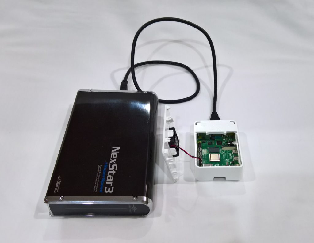
The computers accessing the NVMe Storage Server would include VMware ESXi hosts, Raspberry Pi SBCs, and of course Windows Computers and Workstations.

The focus of this project is on high throughput (in the GB/sec) and IOPS.

The current plan for the storage environment is for video editing, as well as VDI VM storage. This can and will change as the project progresses.

The History

More and more businesses are using all-flash NVMe and SSD based storage systems, so I figured there’s no reason why I can’t have build and have my own budget custom all NVMe flash NAS.

This is the story of how I built my own NVMe based Storage Server.

The first version of the NVMe Storage Server consisted of the IO-PEX40152 card with 4 x 2TB Sabrent Rocket 4 NVMe drives inside of an HPE Proliant DL360p Gen8 Server. The server was running ESXi with TrueNAS virtualized, and the PCIe card passed through to the TrueNAS VM.

The results were great, the performance was amazing, and both servers had access to the NFS export via 2 x 10Gb SFP+ networking.

There were three main problems with this setup:

  1. Virtualized – Once a month I had an ESXi PSOD. This was either due to overheating of the IO-PEX40152 card because of modifications I made, or bugs with the DL360p servers and PCIe passthrough.
  2. NFS instead of iSCSI – Because TrueNAS was virtualized inside of the host that was using it for storage, I had to use NFS since the host virtualizing TrueNAS would also be accessing the data on the TrueNAS VM. When shutting down the host, you need to shut down TrueNAS first. NFS disconnects are handled way healthier than iSCSI disconnects (which can cause corruption even if no files are being used).
  3. CPU Cores maxed on data transfer – When doing initial testing, I was maxing out the CPU cores assigned to the TrueNAS VM because the data transfers were so high. I needed a CPU and setup that was better fit.

Version 1 went great, but you can see some things needed to be changed. I decided to go with a dedicated server, not virtualize TrueNAS, and go for a newer CPU with a higher Ghz speed.

And so, version 2 was born (built). Keep reading and scrolling for pictures!

The Hardware

On version 2 of the project, the hardware includes:
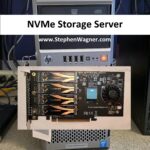
Notes on the Hardware:

  • While the ML310e Gen8 v2 server is a cheap low entry server, it’s been a fantastic team member of my homelab.
  • HPE Dual 10G Port 560SFP+ adapters can be found brand new in unsealed boxes on eBay at very attractive prices. Using HPE Parts inside of HPE Servers, avoids the fans from spinning up fast.
  • The ML310e Gen8 v2 has some issues with passing through PCIe cards to ESXi. Works perfect when not passing through.

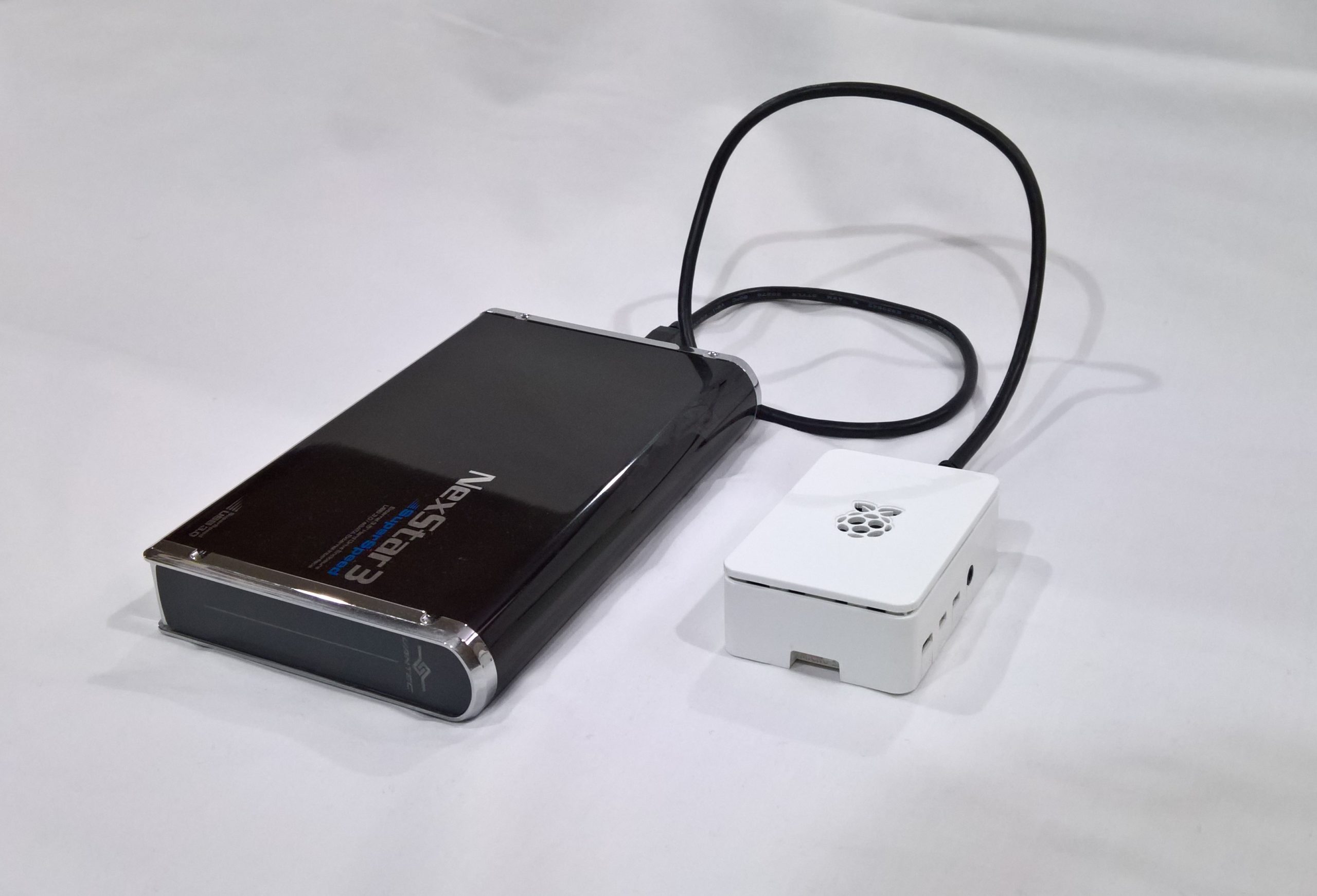
The new NVMe Storage Server

I decided to repurpose an HPE Proliant ML310e Gen8 v2 Server. This server was originally acting as my Nvidia Grid K1 VDI server, because it supported large PCIe cards. With the addition of my new AMD S7150 x2 hacked in/on to one of my DL360p Gen8’s, I no longer needed the GRID card in this server and decided to repurpose it.

Picture of an HPe ML310e Gen8 v2 with NVMe Storage
HPe ML310e Gen8 v2 with NVMe Storage

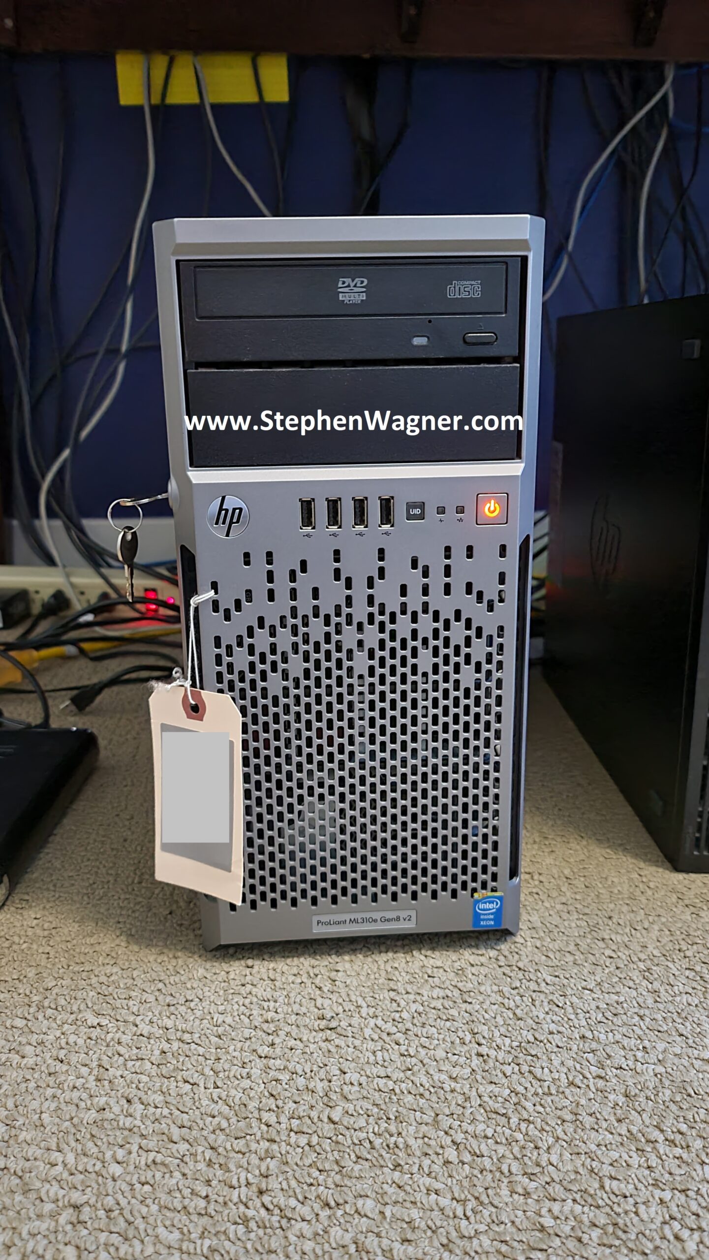
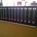
I installed the IOCREST IO-PEX40152 card in to the PCIe 16x slot, with 4 x 2TB Sabrent Rocket 4 NVME drives.

Picture of IOCREST IO-PEX40152 with GLOTRENDS M.2 NVMe SSD Heatsink on Sabrent Rocket 4 NVME
IOCREST IO-PEX40152 with GLOTRENDS M.2 NVMe SSD Heatsink on Sabrent Rocket 4 NVME

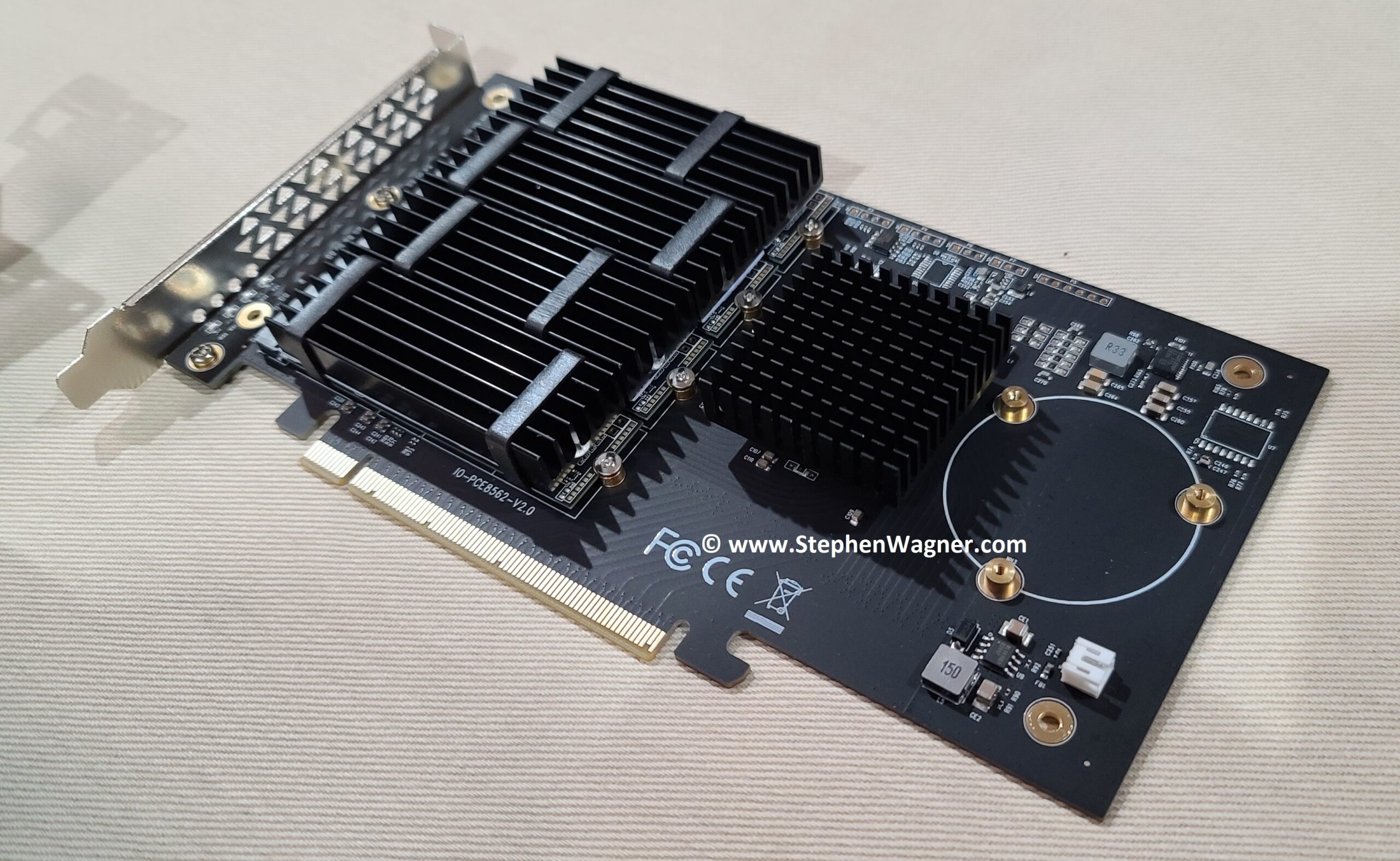
While the server has a PCIe 16x wide slot, it only has an 8x bus going to the slot. This means we will have half the capable speed vs the true 16x slot. This however does not pose a problem because we’ll be maxing out the 10Gb NICs long before we max out the 8x bus speed.

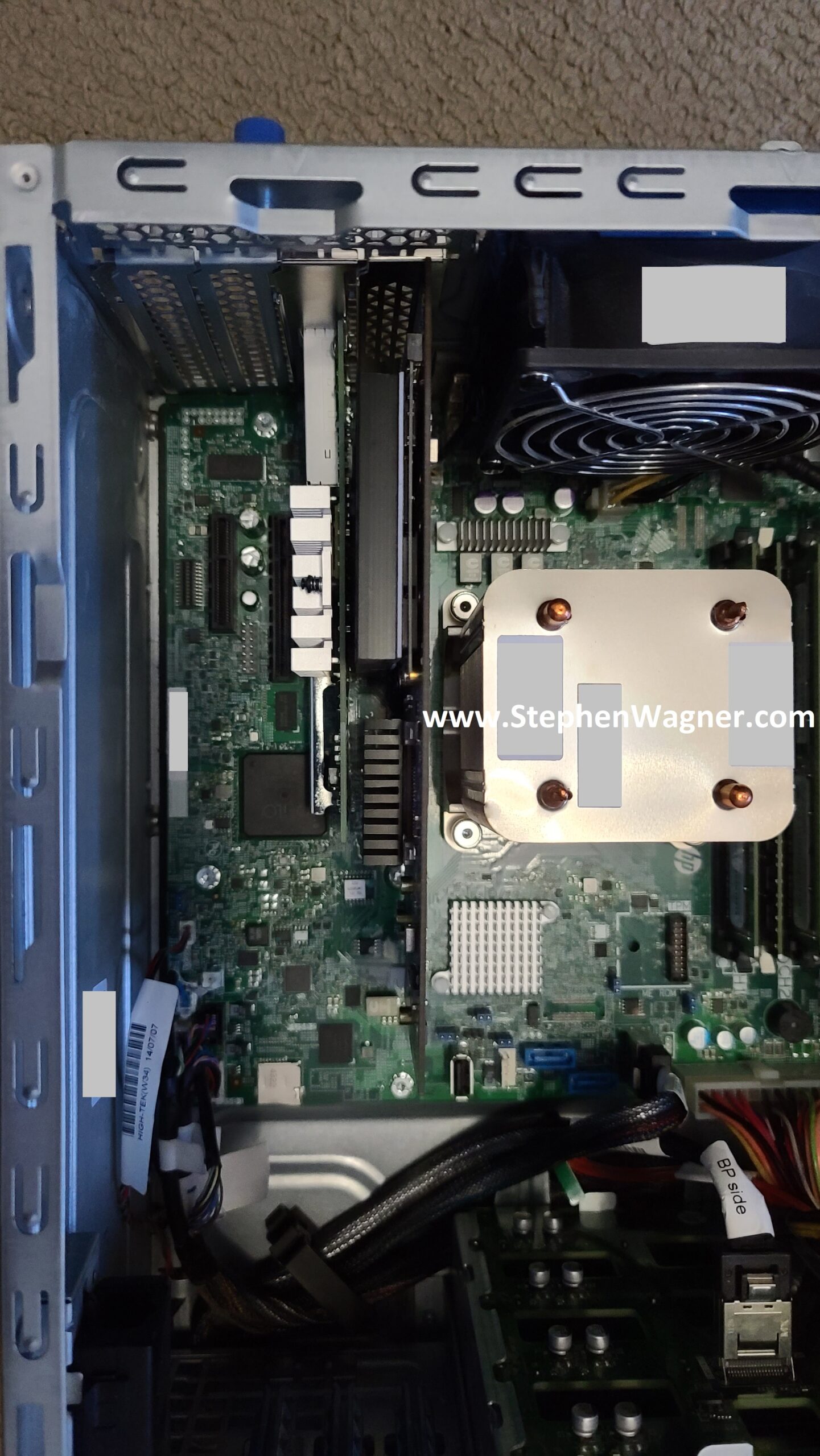
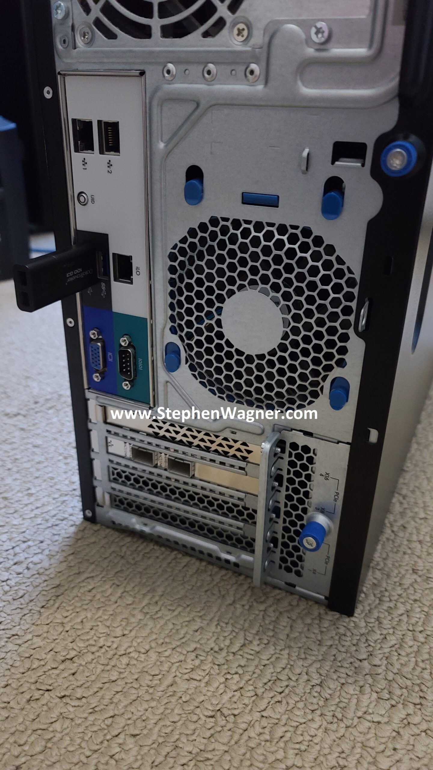
I also installed an HPE Dual Port 560SFP+ NIC in to the second slot. This will allow a total of 2 x 10Gb network connections from the server to the Ubiquiti UniFi US-16-XG 10Gb network switch, the backbone of my network.

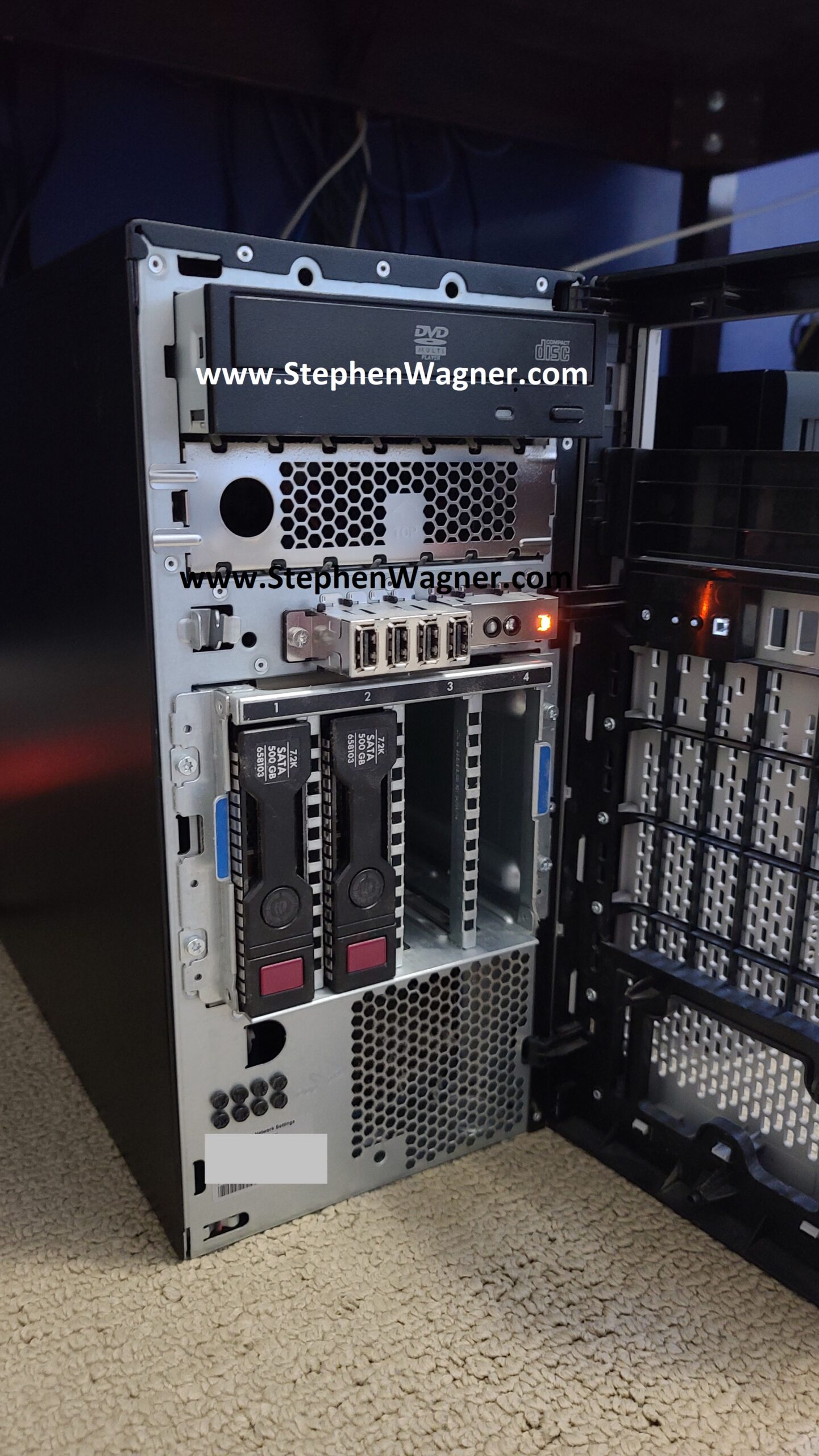
The Server also have 4 x Hot Swappable HD bays on the front. When configured in HBA mode (via the BIOS), these are accessible by TrueNAS and can be used. I plan on populating these with 4 x 4TB HPE MDL SATA Hot Swappable drives to act as a replication destination for the NVMe pool and/or slower magnetic long-term storage.

Front view of HPE ML310e Gen8 v2 with Hotswap Drive bays
HPE ML310e Gen8 v2 with Hotswap Drive bays

I may also try to give WD RED Pro drives a try, but I’m not sure if they will cause the fans to speed up on the server.

TrueNAS Installation and Configuration

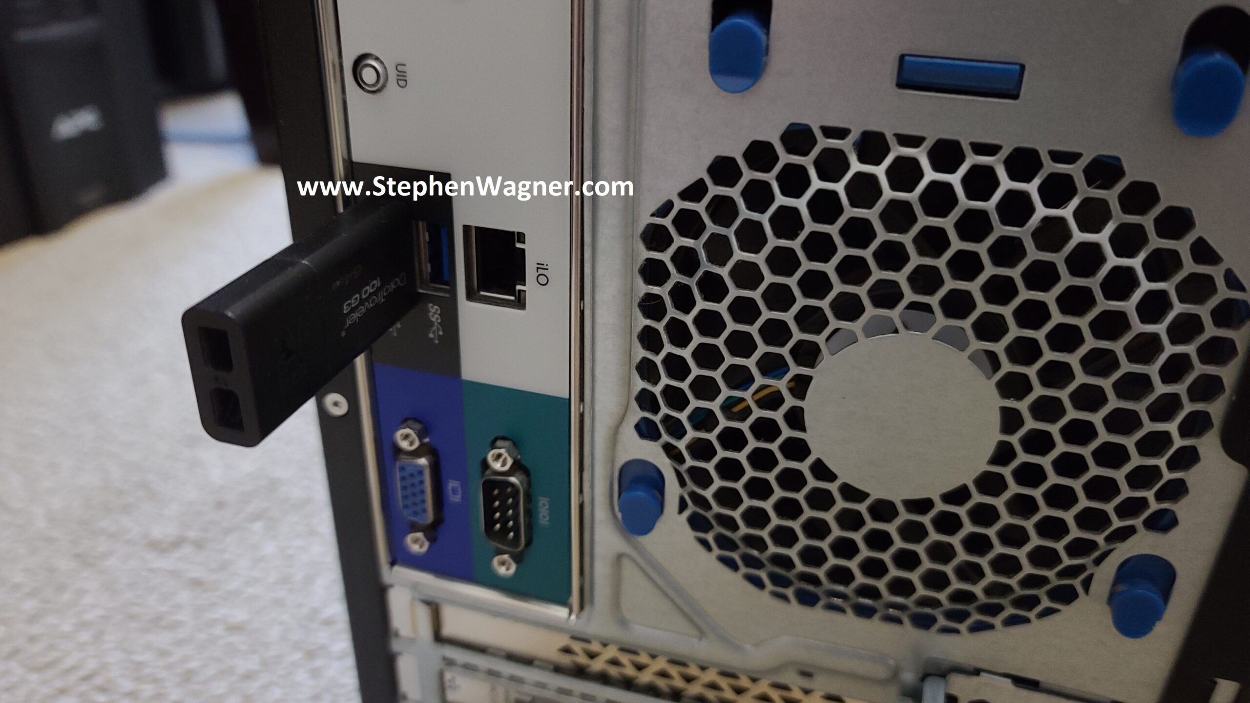
For the initial Proof-Of-Concept for version 2, I decided to be quick and dirty and install it to a USB stick. I also waited until I installed TrueNAS on to the USB stick and completed basic configuration before installing the Quad NVMe PCIe card and 10Gb NIC. I’m using a USB 3.0 port on the back of the server for speed, as I can’t verify if the port on the motherboard is USB 2 or USB 3.

Picture of a TrueNAS USB Stick on HPE ML310e Gen8 v2
TrueNAS USB Stick on HPE ML310e Gen8 v2

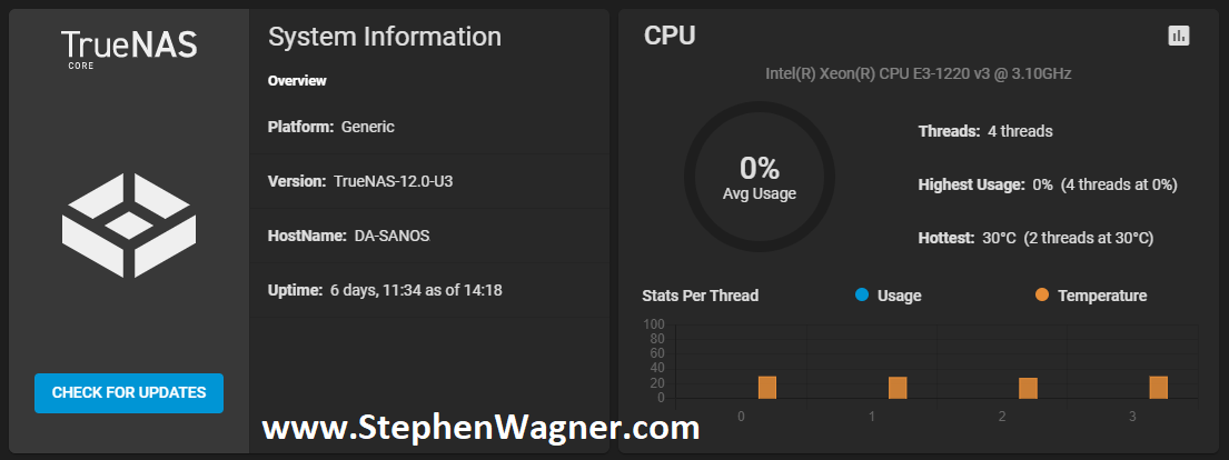
TrueNAS installation worked without any problems whatsoever on the ML310e. I configured the basic IP, time, accounts, and other generic settings. I then proceeded to install the PCIe cards (storage and networking).

Screenshot of TrueNAS Dashboard Installed on NVMe Storage Server
TrueNAS Installed on NVMe Storage Server

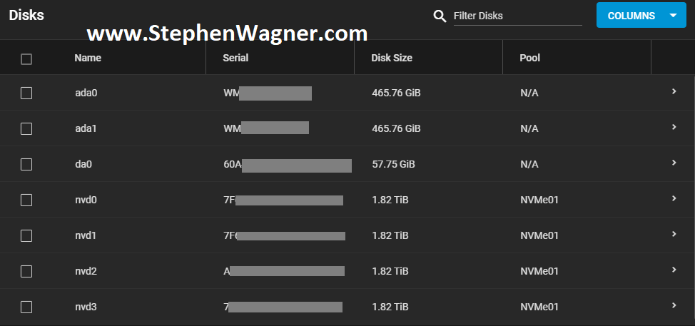
All NVMe drives were recognized, along with the 2 HDDs I had in the front Hot-swap bays (sitting on an HP B120i Controller configured in HBA mode).

Screenshot of available TrueNAS NVMe Disks
TrueNAS NVMe Disks

The 560SFP+ NIC also was detected without any issues and available to configure.

Dashboard Screenshot of TrueNAS 560SFP+ 10Gb NIC
TrueNAS 560SFP+ 10Gb NIC

Storage Configuration

I’ve already done some testing and created a guide on FreeNAS and TrueNAS ZFS Optimizations and Considerations for SSD and NVMe, so I made sure to use what I learned in this version of the project.

I created a striped pool (no redundancy) of all 4 x 2TB NVMe drives. This gave us around 8TB of usable high speed NVMe storage. I also created some datasets and a zVOL for iSCSI.

Screenshot of NVMe TrueNAS Storage Pool with Datasets and zVol
NVMe TrueNAS Storage Pool with Datasets and zVol

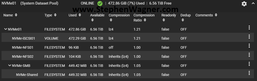
I chose to go with the defaults for compression to start with. I will be testing throughput and achievable speeds in the future. You should always test this in every and all custom environments as the results will always vary.

Network Configuration

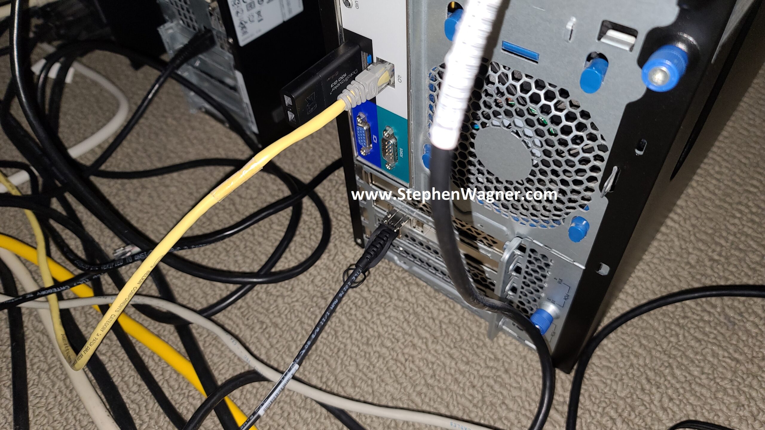
Initial configuration was done via the 1Gb NIC connection to my main LAN network. I had to change this as the 10Gb NIC will be directly connected to the network backbone and needs to access the LAN and Storage VLANs.

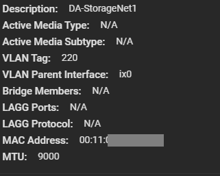
I went ahead and configured a VLAN Interface on VLAN 220 for the Storage network. Connections for iSCSI and NFS will be made on this network as all my ESXi servers have vmknics configured on this VLAN for storage. I also made sure to configure an MTU of 9000 for jumbo frames (packets) to increase performance. Remember that all hosts must have the same MTU to communicate.

Screenshot of 10Gb NIC on Storage VLAN
10Gb NIC on Storage VLAN

Next up, I had to create another VLAN interface for the LAN network. This would be used for management, as well as to provide Windows File Share (SMB/Samba) access to the workstations on the network. We leave the MTU on this adapter as 1500 since that’s what my LAN network is using.

Screenshot of 10Gb NIC on LAN VLAN
10Gb NIC on LAN VLAN

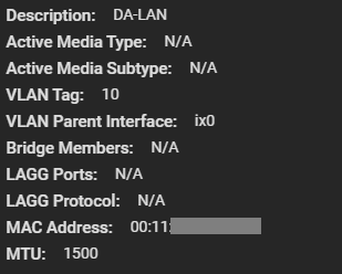
As a note, I had to delete the configuration for the existing management settings (don’t worry, it doesn’t take effect until you hit test) and configure the VLAN interface for my LANs VLAN and IP. I tested the settings, confirmed it was good, and it was all setup.

At this point, only the 10Gb NIC is now being used so I went ahead and disconnected the 1Gb network cable.

Sharing Setup and Configuration

It’s now time to configure the sharing protocols that will be used. As mentioned before, I plan on deploying iSCSI, NFS, and Windows File Shares (SMB/Samba).

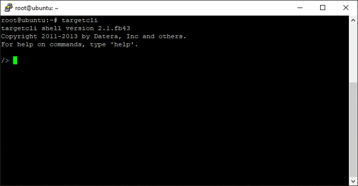
iSCSI and NFS Configuration

Normally, for a VMware ESXi virtualization environment, I would always usually prefer iSCSI based storage, however I also wanted to configure NFS to test throughput of both with NVMe flash storage.

Earlier, I created the datasets for all my my NFS exports and a zVOL volume for iSCSI.

Note, that in order to take advantage of the VMware VAAI storage directives (enhancements), you must use a zVOL to present an iSCSI target to an ESXi host.

For NFS, you can simply create a dataset and then export it.

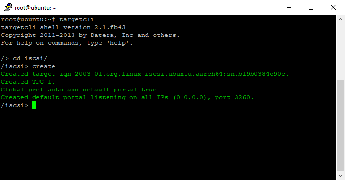
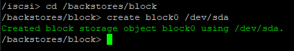
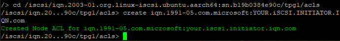
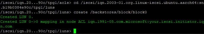
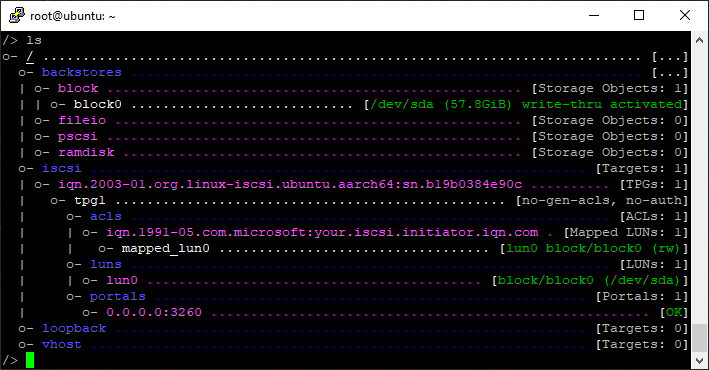
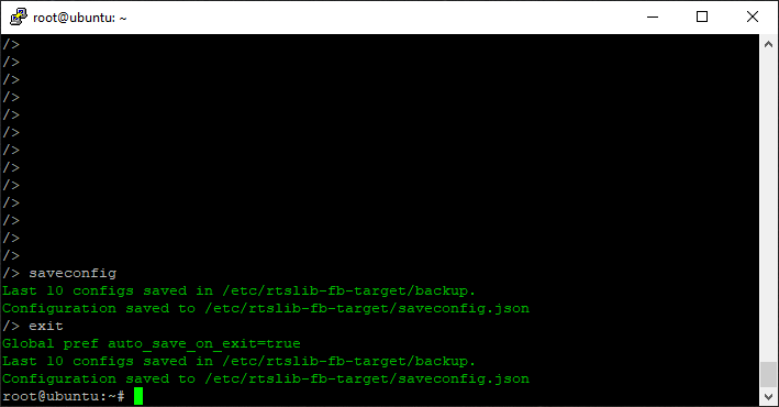
For iSCSI, you need to create a zVol and then configure the iSCSI Target settings and make it available.

SMB (Windows File Shares)

I needed to create a Windows File Share for file based storage from Windows computers. I plan on using the Windows File Share for high-speed storage of files for video editing.

Using the dataset I created earlier, I configured a Windows Share, user accounts, and tested accessing it. Works perfect!
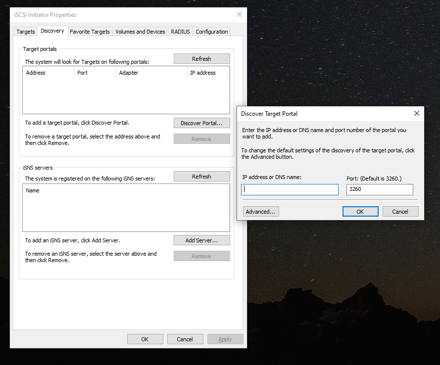
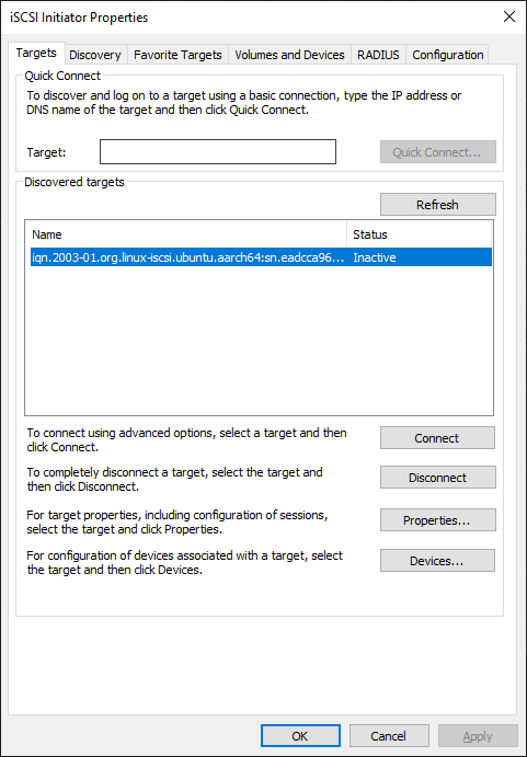
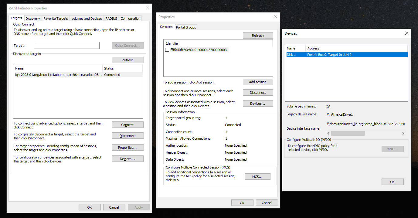
Connecting the host

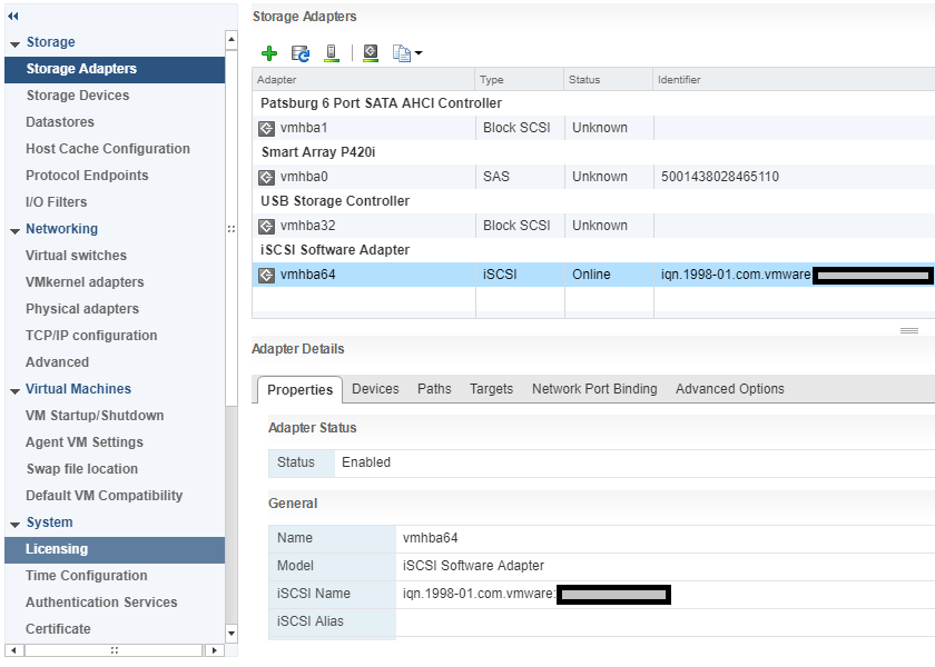
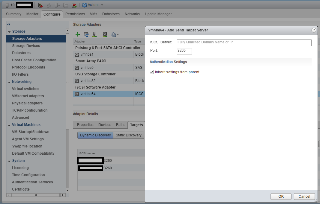
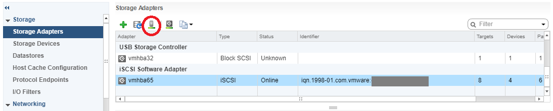
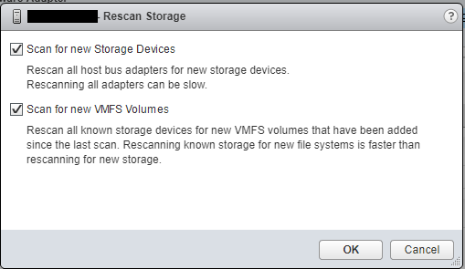
Connecting the ESXi hosts to the iSCSI targets and the NFS exports is done in the exact same way that you would with any other storage system, so I won’t be including details on that in this post.

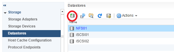
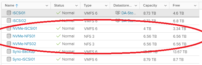
We can clearly see the iSCSI target and NFS exports on the ESXi host.

Screenshot of TrueNAS NVMe iSCSI Target on VMware ESXi Host
TrueNAS NVMe iSCSI Target on VMware ESXi Host
Screenshot of NVMe iSCSI and NFS ESXi Datastores
NVMe iSCSI and NFS ESXi Datastores

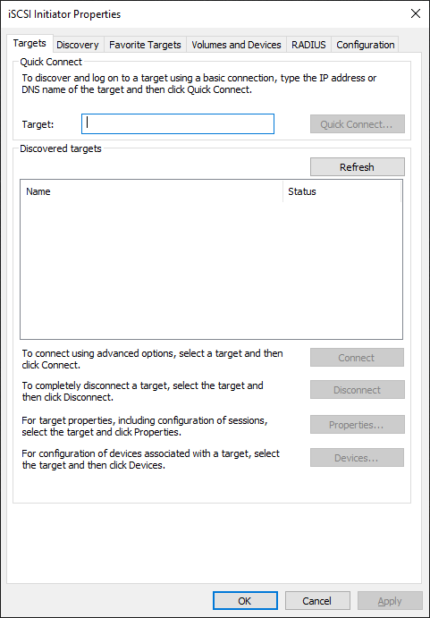
To access Windows File Shares, we log on and map the network share like you would normally with any file server.

Testing

For testing, I moved (using Storage vMotion) my main VDI desktop to the new NVMe based iSCSI Target LUN on the NVMe Storage Server. After testing iSCSI, I then used Storage vMotion again to move it to the NFS datastore. Please see below for the NVMe storage server speed test results.

Speed Tests

Just to start off, I want to post a screenshot of a few previous benchmarks I compiled when testing and reviewing the Sabrent Rocket 4 NVMe SSD disks installed in my HPE DL360p Gen8 Server and passed through to a VM (Add NVMe capability to an HPE Proliant DL360p Gen8 Server).

Screenshot of CrystalDiskMark testing an IOCREST IO-PEX40152 and Sabrent Rocket 4 NVME SSD for speed
CrystalDiskMark testing an IOCREST IO-PEX40152 and Sabrent Rocket 4 NVME SSD
Screenshot of CrystalDiskMark testing IOPS on an IOCREST IO-PEX40152 and Sabrent Rocket 4 NVME SSD
CrystalDiskMark testing IOPS on an IOCREST IO-PEX40152 and Sabrent Rocket 4 NVME SSD

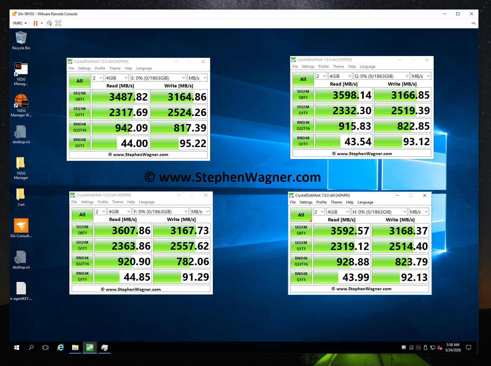
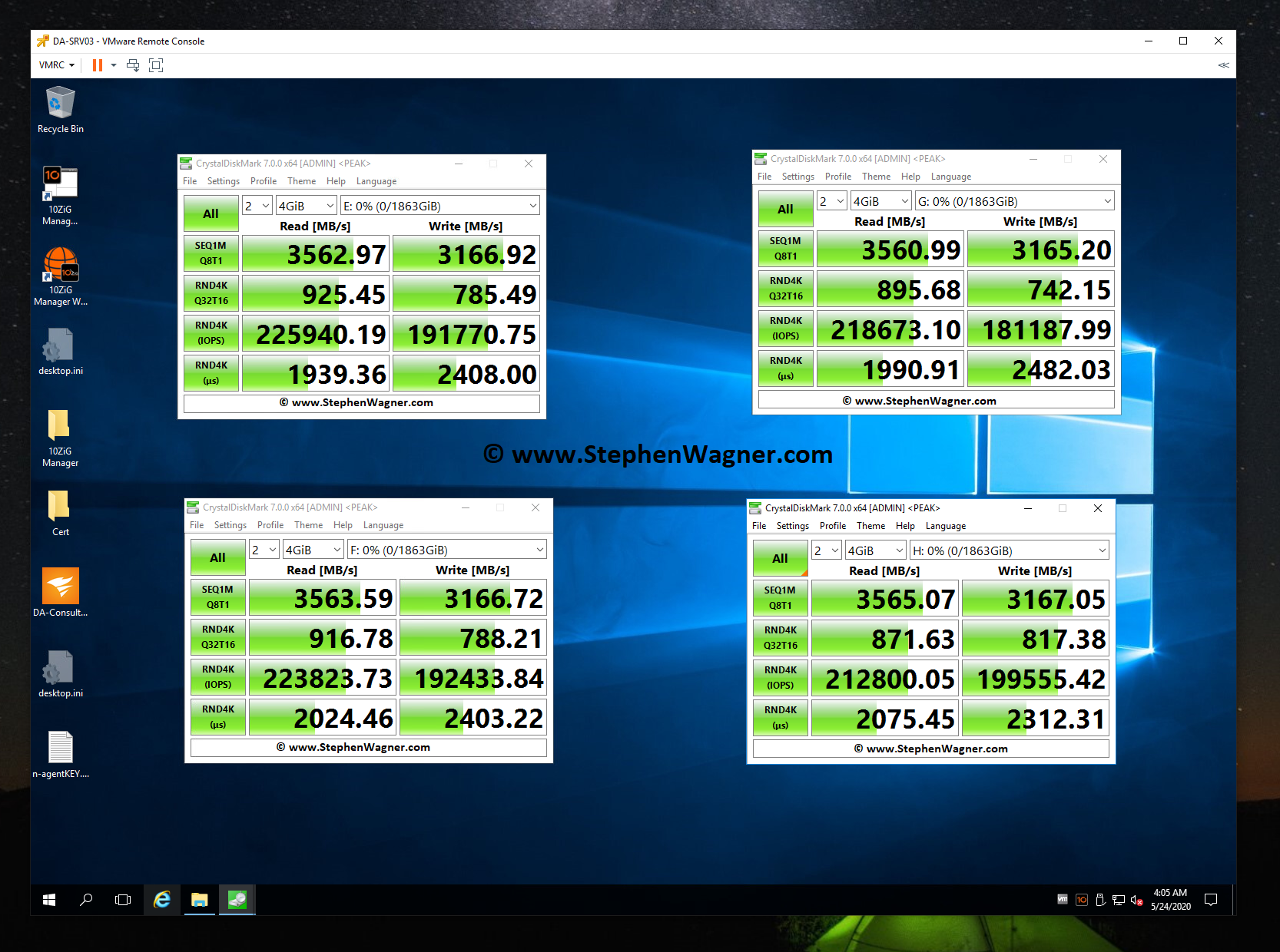
Note, that when I performed these tests, my CPU was maxed out and limiting the actual throughput. Even then, these are some fairly impressive speeds. Also, these tests were directly testing each NVMe drive individually.

Moving on to the NVMe Storage Server, I decided to test iSCSI NVMe throughput and NFS NVMe throughput.

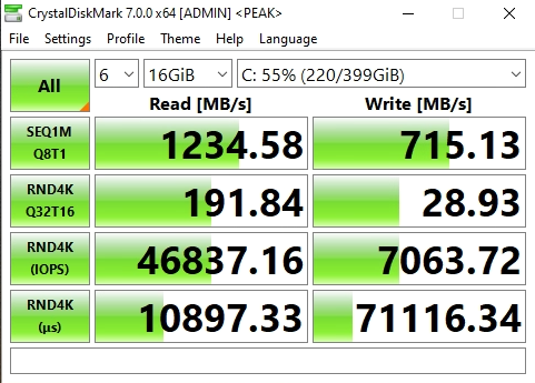
I opened up CrystalDiskMark and started a generic test, running a 16GB test file a total of 6 times on my VDI VM sitting on the iSCSI NVMe LUN.

Screenshot of NVMe Storage Server iSCSI Benchmark with CrystalDiskMark
NVMe Storage Server iSCSI Benchmark with CrystalDiskMark

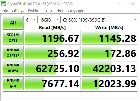
You can see some impressive speeds maxing out the 10Gb NIC with crazy performance of the NVME storage:

  • 1196MB/sec READ
  • 1145.28MB/sec WRITE (Maxing out the 10GB NIC)
  • 62,725.10 IOPS READ
  • 42,203.13 IOPS WRITE

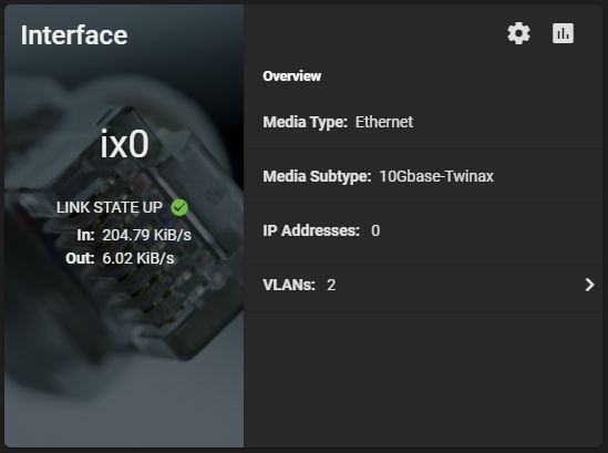
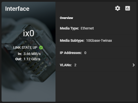
Additionally, here’s a screenshot of the ix0 NIC on the TrueNAS system during the speed test benchmark: 1.12 GiB/s.

Screenshot of TrueNAS NVME Maxing out 10Gig NIC
TrueNAS NVME Maxing out 10Gig NIC

And remember this is with compression. I’m really excited to see how I can further tweak and optimize this, and also what increases will come with configuring iSCSI MPIO. I’m also going to try to increase the IOPS to get them closer to what each individual NVMe drive can do.

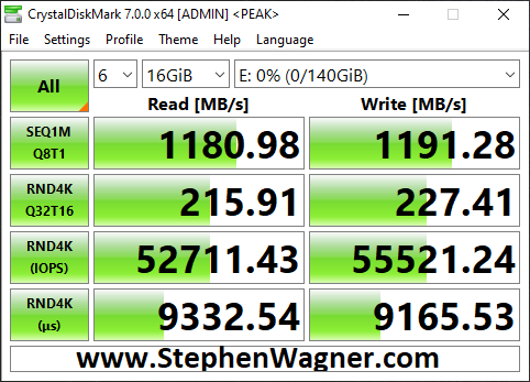
Now on to NFS, the results were horrible when moving the VM to the NFS Export.

Screenshot of NVMe Storage Server NFS Benchmark with CrystalDiskMark
NVMe Storage Server NFS Benchmark with CrystalDiskMark

You can see that the read speed was impressive, but the write speed was not. This is partly due to how writes are handled with NFS exports.

Clearly iSCSI is the best performing method for ESXi host connectivity to a TrueNAS based NVMe Storage Server. This works perfect because we’ll get the VAAI features (like being able to reclaim space).

iSCSI MPIO Speed Test

This is more of an update… I was finally able to connect, configure, and utilize the 2nd 10Gbe port on the 560SFP+ NIC. In my setup, both hosts and the TrueNAS storage server all have 2 connections to the switch, with 2 VLANs and 2 subnets dedicated to storage. Check out the before/after speed tests with enabling iSCSI MPIO.

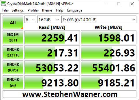
As you can see I was able to essentially double my read speeds (again maxing out the networking layer), however you’ll notice that the write speeds maxed out at 1598MB/sec. I believe we’ve reached a limitation of the CPU, PCIe bus, or something else inside of the server. Note, that this is not a limitation of the Sabrent Rocket 4 NVME drives, or the IOCREST NVME PCIe card.

Moving Forward

I’ve had this configuration running for around a week now with absolutely no issues, no crashes, and it’s been very stable.

Using a VDI VM on NVMe backed storage is lightning fast and I love the experience.

I plan on running like this for a little while to continue to test the stability of the environment before making more changes and expanding the configuration and usage.

Future Plans (and Configuration)

  • Drive Bays
    • I plan to populate the 4 hot-swappable drive bays with HPE 4TB MDL drives. Configured with RaidZ1, this should give me around 12TB usable storage. I can use this for file storage, backups, replication, and more.
  • NVMe Replication
    • This design was focused on creating non-redundant extremely fast storage. Because I’m limited to a total of 4 NVMe disks in this design, I chose not to use RaidZ and striped the data. If one NVMe drive is lost, all data is lost.
    • I don’t plan on storing anything important, and at this point the storage is only being used for VDI VMs (which are backed up), and Video editing.
    • If I can populate the front drive bays, I can replicate the NVMe storage to the traditional HDD storage on a frequent basis to protect against failure to some level or degree.
  • Version 3 of the NVMe Storage Server
    • More NVMe and Bigger NVMe – I want more storage! I want to test different levels of RaidZ, and connect to the backbone at even faster speeds.
    • NVME Drives with PLP (Power Loss Prevention) for data security and protection.
    • Dual Power Supply

Let me know your thoughts and ideas on this setup!

Mar 182020
 
Raspberry Pi iSCSI Target with external USB drive attached

The Raspberry Pi 4 is a super neat little device that has a whole bunch of uses, and if there isn’t for something you’re looking for you can make one! As they come out with newer and newer generations of the Raspberry Pi, the hardware gets better, faster, and the capabilities greatly improve.

I decided it was time with the newer and powerful Raspberry Pi 4, to try and turn it in to an iSCSI SAN! Yes, you heard that right!

With the powerful quad core processor, mighty 4GB of RAM, and USB 3.0 ports, there’s no reason why this device couldn’t act as a SAN (in the literal sense). You could even use mdadm and configure it as a SAN that performs RAID across multiple drives.

Picture of a Raspberry Pi 4 with External USB 3 HD setup as an iSCSI Target and SAN
Raspberry Pi 4 with External USB 3 HD

In this article, I’m going to explain what, why, and how to (with full instructions) configure your Raspberry Pi 4 as an iSCSI SAN, an iSCSI Target.

Please Note: these instructions also apply to standard Linux PCs and Servers as well, but I’m putting emphasis that you can do this on SBCs like the Raspberry Pi.

A little history…

Over the years on the blog, I’ve written numerous posts pertaining to virtualization, iSCSI, storage, and other topics because of my work in IT. On the side as a hobby I’ve also done a lot of work with SBC (Single Board Computers) and storage.

Some of the most popular posts, while extremely old are:

You’ll notice I put a lot of effort specifically in to “Lio-Target”…

When deploying or using Virtualization workloads and using shared iSCSI storage, the iSCSI Target must support something called SPC-3/SPC-4 Reservations.

SPC-3 and SPC-4 reservations allow a host to set a “SCSI reservation” and reserve the blocks on the storage it’s working with. By reserving the storage blocks, this allows numerous hosts to share the storage. Ultimately this is what allows you to have multiple hosts accessing the same volume. Please keep in mind both the iSCSI Target and the filesystem must support clustered filesystems and multiple hosts.

Originally, most of the open source iSCSI targets including the one that was built in to the Linux kernel did not support SCSI reservations. This resulted in volume and disk corruption when someone deployed a target and connected with multiple hosts.

Lio-Target specifically supported these reservations and this is why it had my focus. Deploying a Lio-target iSCSI target fully worked when using with VMware vSphere and VMware ESXi.

Ultimately, on January 15th, 2011 the iSCSI target in the Linux kernel 2.6.38 was replaced with Lio-target. All new Linux kernels use the Lio-Target as it’s iSCSI target.

What is an iSCSI Target?

An iSCSI target is a target that contains LUNs that you connect to with an iSCSI initiator.

The Target is the server, and the client is the initiator. Once connected to a target, you can directly access volumes and LUNs using iSCSI (SCSI over Internet).

What is it used for?

iSCSI is mostly used as shared storage for virtual environments like VMware vSphere (and VMware ESXi), as well as Hyper-V, and other hypervisors.

It can also be used for containers, file storage, remote access to drives, etc…

Why would I use or need this on the Raspberry Pi 4?

Some users are turning their Raspberry Pi’s in to NAS devices, whynot turn it in to a SAN?

With the powerful processor, 4GB of RAM, and USB 3.0 ports (for external storage), this is a perfect platform to act as a testbed or homelab for shared storage.

For virtual environments, if you wanted to learn about shared storage you could deploy the Raspberry Pi iSCSI target and connect to it with one or more ESXi hosts.

Or you could use this to remotely connect to a disk on a direct block level, although I’d highly recommend doing this over a VPN.

How do you connect to an iSCSI Target?

As mentioned above, you normally connect to an iSCSI Target and volume or LUN using an iSCSI initiator.

Using VMware ESXi, you’d most likely use the “iSCSI Software Adapter” under storage adapters. To use this you must first enable and configure it under the Host -> Configure -> Storage Adapters.

Image of the iSCSI Initiator software adapter configuration on VMware vSphere of an ESXi host.
VMware vSphere Host iSCSI Initiator Software Adapter

Using Windows 10, you could use the iSCSI initiator app. To use this simply search for “iSCSI Initiator” in your search bar, or open it from “Administrative Tools” under the “Control Panel”.

The Windows 10 iSCSI Initiator (iSCSI Properties) window.
Windows 10 iSCSI Initiator (iSCSI Properties)

There is also a Linux iSCSI initiator that you can use if you want to connect from a Linux host.

What’s needed to get started?

To get started using this guide, you’ll need the following:

  • Raspberry Pi 4
  • Ubuntu Server for Raspberry Pi or Raspbian
  • USB Storage (External HD, USB Stick, preferably USB 3.0 for speed)
  • A client device to connect (ESXi, Windows, or Linux)
  • Networking gear between the Raspberry Pi target and the device acting as the initiator

Using this guide, we’re assuming that you have already installed, are using, and have configured linux on the Raspberry Pi (setup accounts, and configured networking).

The Ubuntu Server image for Raspberry Pi comes ready to go out of the box as the kernel includes modules for the iSCSI Target pre-built. This is the easier way to set it up.

These instructions can also apply to Raspbian Linux for Raspberry Pi, however Raspbian doesn’t include the kernel modules pre-built for the iSCSI target and there are minor name differences in the apps. This is more complex and requires additional steps (including a custom kernel to be built).

Let’s get started, here’s the instructions…

If you’re running Raspbian, you need to compile a custom kernel and build the iSCSI Target Core Modules. Please follow my instructions (click here) to compile a custom kernel on Raspbian or Raspberry Pi. When you’re following my custom kernel build guide, in addition after running “make menuconfig”:

  1. Navigate to “Device Drivers”.
  2. Select (using space bar) “Generic Target Core Mod (TCM) and ConfigFS Infrastructure” so that it has an <M> (for module) next to it. Then press enter to open it. Example below.
    <M> Generic Target Core Mod (TCM) and ConfigFS Infrastructure
  3. Select all the options as <M> so that they compile as a kernel module, as shown below.
     --- Generic Target Core Mod (TCM) and ConfigFS Infrastructure
    <M> TCM/IBLOCK Subsystem Plugin for Linux/BLOCK
    <M> TCM/FILEIO Subsystem Plugin for Linux/VFS
    <M> TCM/pSCSI Subsystem Plugin for Linux/SCSI
    <M> TCM/USER Subsystem Plugin for Linux
    <M> TCM Virtual SAS target and Linux/SCSI LDD Fabcric loopback module
    <M> Linux-iSCSI.org iSCSI Target Mode Stack
  4. Save the kernel config and continue following the “compile a custom raspberry pi kernel” guide steps.

If you’re running Ubuntu Server, the Linux kernel was already built with these modules so the action above is not needed.

We’re going to assume that the USB drive or USB stick you’ve installed is available on the system as “/dev/sda” for the purposes of this guide. Also please note that when using the create commands in the entries below, it will create it’s own unique identifiers on your system different from mine, please adjust your commands accordingly.

Let’s start configuring the Raspberry Pi iSCSI Target!

  1. First we need to install the targetcli interface to configure the target.
    As root (or use sudo) run the following command if you’re running Ubuntu Server.
    apt install targetcli-fb
    As root (or use sudo) run the following command if you’re running Raspbian.
    apt install targetcli
  2. As root (or using sudo) run “targetcli”.
    targetcli
    Running the targetcli command
  3. Create an iSCSI Target and Target Port Group (TPG).
    cd iscsi/
    create
    Command to create a TPG iSCSI Target
  4. Create a backstore (the physical storage attached to the Raspberry Pi).
    cd /backstores/block
    create block0 /dev/sda
    Creating an iSCSI Target Backstore command
  5. Create an Access Control List (ACL) for security and access to the Target.
    cd /iscsi/iqn.2003-01.org.linux-iscsi.ubuntu.aarch64:sn.eadcca96319d/tpg1/acls
    create iqn.1991-05.com.microsoft:your.iscsi.initiator.iqn.com
    Creating an ACL inside of targetcli for the iSCSI Target
  6. Add, map, and assign the backstore (block storage) to the iSCSI Target LUN and ACL.
    cd /iscsi/iqn.2003-01.org.linux-iscsi.ubuntu.aarch64:sn.eadcca96319d/tpg1/luns
    create /backstores/block/block0
    Mapping a backstore to LUN and ACL in TargetCLI
  7. Review your configuration.
    cd /
    ls
    Reviewing the configuration in TargetCLI
  8. Save your configuration and exit.
    saveconfig
    exit
    Saving the configuration and exiting the targetcli interface

That’s it, you can now connect to the iSCSI target via an iSCSI initiator on another machine.

For a quick example of how to connect, please see below.

Connect the ESXi Initiator

To connect to the new iSCSI Target on your Raspberry Pi, open up the configuration for your iSCSI Software Initiator on ESXi, go to the targets tab, and add a new iSCSI Target Server to your Dynamic Discovery list.

Add iSCSI Server to the Dynamic Discovery list on the iSCSI Software Initiator on ESXi
ESXi adding iSCSI Target Server (SAN) to iSCSI Software Initiator Dynamic Discovery

Once you do this, rescan your HBAs and the disk will now be available to your ESXi instance.

Connect the Windows iSCSI Initiator

To connect to the new iSCSI Target on Windows, open the iSCSI Initiator app, go to the “Discovery” tab, and click on the “Discover Portal” button.

Adding an iSCSI Target Server to the Windows iSCSI Software Initiator
Add iSCSI Target Server to Windows iSCSI Initiator

In the new window, add the IP address of the iSCSI Target (your Raspberry Pi), and hit ok, then apply.

Now on the “Targets” tab, you’ll see an entry for the discovered target. Select it, and hit “Connect”.

The targets list on Windows iSCSI Software Initiator
Windows iSCSI Initiator Targets List

You’re now connected! The disk will show up in “Disk Management” and you can now format it and use it!

Here’s what an active connection looks like.

The Microsoft iSCSI Initiator window open, showing an active connection to an iSCSI target, and iSCSI disk
Windows 10 iSCSI Initiator connect to iSCSI Target presenting a disk

That’s all folks!

Conslusion

There you have it, you now have a beautiful little Raspberry Pi 4 acting as a SAN and iSCSI Target providing LUNs and volumes to your network!

Picture of Raspberry Pi 4 iSCSI Target running Ubuntu Server with External USB 3 HD
Raspberry Pi 4 iSCSI Target with External USB 3 HD

Leave a comment and let me know how you made out or if you have any questions!

Jul 312019
 

Once I upgraded my Synology NAS to DSM 6.2 I started to experience frequent lockups and freezing on my DS1813+. The Synology DS1813+ would become unresponsive and I wouldn’t be able to SSH or use the web GUI to access it. In this state, NFS sometimes would become unresponsive.

When this occured, I would need to press and hold the power button to force it to shutdown, or pull the power. This is extremely risky as it can cause data corruption.

I’m currently running DSM 6.2.2-24922 Update 2.

The cause

This occurred for over a month until it started to interfere with ESXi hosts. I also noticed that the issue would occur when restarting any of my 3 ESXi hosts, and would definitely occur if I restarted more than one.

During the restarting, while logged in to the web GUI and SSH, I was able to see that the memory (RAM) usage would skyrocket. Finally the kernel would panic and attempt to reduce memory usage once the swap file had filled up (keep in mind my DS1813+ has 4GB of memory).

Analyzing “top” as well as looking at processes, I noticed the Synology index service was causing excessive memory and CPU usage. On a fresh boot of the NAS, it would consume over 500MB of memory.

The fix (Please scroll down and see updates)

In my case, I only use my Synology NAS for an NFS/iSCSI datastore for my ESXi environment, and do not use it for SMB (Samba/File Shares), so I don’t need the indexing service.

I went ahead and SSH’ed in to the unit, and ran the following commands to turn off the service. Please note, this needs to be run as root (use “sudo su” to elevate from admin to root).

synoservice --disable pkgctl-SynoFinder

While it did work, and the memory was instantly freed, the setting did not stay persistant on boot. To uninstalling the Indexing service, run the following command.

synopkg uninstall SynoFinder

Doing this resolved the issue and freed up tons of memory. The unit is now stable.

Update May 31st, 2020 – Increased Stability

After troubleshooting I noticed that the majority of stability issues would start occurring when ESXi hosts accessing NFS exports on the Synology diskstation are restarted.

I went ahead and stopped using NFS, started using iSCSI with MPIO, and the stability of the Synology NAS has greatly improved. I will continue to monitor this.

I still have plans to hack the Synology NAS and put my own OS on it.

Update May 2nd, 2020 – It’s still crashing, and really frustrating me

Today I had to restart my 3 ESXi hosts that are connected to the NFS export on the Synology Disk Station. After restarting the hosts, the Synology device has gone in to a lock-up state once again. It appears the issue is still present.

The device is responding to pings, and still provides access to SMB and NFS, but the web GUI, SSH, and console access is unresponsive.

I’m officially going to start planning on either retiring this device as this is unacceptable, especially in addition to all the issues over the years, or I may try an attempt at hacking the Synology Diskstation to run my own OS.

Update April 21st, 2020 – What I thought was the fix

After a few more serious crashes and lockups, I finally decided to do something about this. I went ahead and backed up my data, deleted the arrays, performed a factory reset on the Synology Disk Station. I also zero’d the metadata and MBR off all the drives.

I then configured the Synology NAS from scratch, used Btrfs (instead of ext4), restored the backups.

The NAS now appears to be running great and has not suffered any lockups or crashses since. I’ve also been noticing that memory management is working a lot better.

I have a feeling that this issue was caused due to the long term chaining of updates (numerous updates installed over time), or the use of the ext4 filesystem.

Update March 20th, 2020

As of March 2020 this issue is still occurring on numerous new firmware updates and version. I’ve tried reaching out to Synology on twitter directly a few times about this issue as well as e-mail (indirectly regarding something else) and have still not received or heard a response. As of this time the issue is still occurring on a regular basis on DSM 6.2.2-24922 Update 4. I’ve taken production and important workloads of the device since I can’t have the device continuously crashing or freezing overnight.

Update – August 16th, 2019

My Synology NAS has been stable since I applied the fix, however after an uptime of a few weeks, I noticed that when restarting servers, the memory usage does hike up (example, from 6% to 46%). However, with the fixes applied above, the unit is stable and no longer crashes.

Oct 202018
 

On an ESXi host when performing a manual unmap on your storage datastore, you may notice a very large (hidden) file on the datastore root called “.asyncUnmapFile”. This file could be taking up terabytes of space, and you aren’t able to delete this file.

asyncUnmapFile

Typically the asyncUnmapFile is used by the UNMAP feature on ESXi hosts to deal with unmapping and unallocating storage blocks on the SAN. When you run a manual UNMAP, this file should be created and should appear to using “0” (no) space (even if it is). When an UNMAP completes, this file should disappear and be automatically removed by the function. If an UNMAP is interupted, this file will not be deleted, allowing you to restart the process and upon a full successful completion, it should then be deleted.

The Problem

Some time ago, I had an issue when performing a manual UNMAP, where the ESXi host became unresponsive (due to memory issues). The command appeared to be completed, however I believe it caused potential issues or corruption on the iSCSI datastore. In subsequent runs, the UNMAP appeared to be functioning and working, however I didn’t realize that the asyncUnmapFile had grown to around 1.5TB.

This was noticed during a SAN storage audit, where we saw that the virtual pool on the SAN was using up way more storage than it should be on the datastore.

When we identified the file was this large and causing issues, we attempted to perform 2 UNMAPs (different reclaim sizes) to see if it would be automatically cleared afterwards. It had no effect and the file was unchanged.

We also tried to modify the permissions on the file, however when trying to delete it, it would report that the file or folder was not found, or that it does not exist. This was concerning as we were worried about potential datastore corruption.

It was also noticed that in the hostd.log and vmkernel.log we saw some errors where the host believed that the blocks on the datastore had already been freed: “on volume labeled ‘iSCSIDatastore01’ already freed by another host: This may be a non-issue”

The Solution

Unfortunately with all the research we did, we couldn’t find a clear-cut solution. With worries that the datastore may be corrupted, we needed to do something.

A decision was ultimately made to Storage vMotion all the VMs (Virtual Machines) to another datastore on a separate storage pool, delete the now empty LUN, and recreate it from scratch. After this, we used Storage vMotion again to move the VMs back.

Instantly I noticed that the VMs on that datastore were running faster (it’s only been 12 hours, so I’ll be adding an update in a few days to confirm). We no longer have the file on any of our datastores.

If anyone has further insight in to this issue, please leave a comment!

Aug 272018
 
Right side of MSA 2040

So, what happens in a worst-case scenario where your backup system fails, you don’t have any VM snapshots, and the last thing standing in the way of complete data loss is your SAN storage systems LUN snapshots?

Well, first you fire whoever purchased and implemented the backup system, then secondly you need to start restoring the VM (or VMs) from your SAN LUN snapshots.

While I’ve never had to do this in the past (all the disaster recovery solutions I’ve designed and sold have been tested and function), I’ve always been curious what the process is and would be like. Today I decided to try it out and develop a procedure for restoring a VM from SAN Storage LUN snapshot.

For this test I pretended a VM was corrupt on my VMware vSphere cluster and then restored it to a previous state from a LUN snapshot on my HPE MSA 2040 (identical for the HPE MSA 2050, and MSA 2052) Dual Controller SAN.

To accomplish the restore, we’ll need to create a host mapping on the SAN for the LUN snapshot to a new LUN number available to the hosts. We then need to add and mount the VMFS volume (residing on the snapshot) to the host(s) while assigning it a new signature and then vMotion the VM from the snapshot’s VMFS to original datastore.

Important Notes (Read first):

  • When mounting a VMFS volume from a SAN snapshot, you MUST RE-SIGNATURE THE SNAPSHOT VMFS volume. Not doing so can cause problems.
  • The snapshot cannot be mapped as read only, VMFS volumes must be marked as writable in order to be mounted on ESXi hosts.
  • You must follow the proper procedure to gracefully dismount and detach the VMFS volume and storage device before removing the snapshot’s host mapping on the SAN.
  • We use Storage vMotion to perform a high-speed move and recovery of the VM. If you’re not licensed for Storage vMotion, you can use the datastore file browser and copy/move from the snapshot VMFS volume to live production VMFS volume, however this may be slower.
  • During this entire process you do not touch, modify, or change any settings on your existing active production LUNs (or LUN numbers).
  • Restoring a VM from a SAN LUN snapshot will restore a crash consistent copy of the VM. The VM when recovered will believe a system crash occurred and power was lost. This is NOT a graceful application consistent backup and restore.
  • Please read your SAN documentation for the procedure to access SAN snapshots, and create host mappings. With the MSA 2040 I can do this live during production, however your SAN may be different and your hosts may need to be powered off and disconnected while SAN configuration changes are made.
  • Pro tip: You can also power on and initialize the VM from the snapshot before initiating the storage vMotion. This will allow you to get production services back online while you’re moving the VM from the snapshot to production VMFS volumes.
  • I’m not responsible if you damage, corrupt, or cause any damage or issues to your environment if you follow these procedures.

We are assuming that you have already either deleted the damaged VM, or removed it from your inventory and renamed the VMs folder on the live VMFS datastore to change the name (example, renaming the folder from “SRV01” to “SRV01.bad”. If you renamed the damaged VM, make sure you have enough space for the new restored VM as well.

Procedure:

Mount the VMFS volume on the LUN snapshot to the ESXi host(s)
  1. Identify the VM you want to recover, write it down.
  2. Identify the datastore that the VM resides on, write it down.
  3. Identify the SAN and identify the LUN number that the VMFS datastore resides on, write it down.
  4. Identify the LUN Snapshot unique name/id/number and write it down, confirm the timestamp to make sure it will contain a valid recovery point.
  5. Log on to the SAN and create a host mapping to present the snapshot (you recorded above) to the hosts using a new and unused LUN number.
  6. Log on to your ESXi host and navigate to configuration, then storage adapters.
  7. Select the iSCSI initator and click the “Rescan Storage Adapters” button to rescan all iSCSI LUNs.

    VMware ESXi Host Rescan Storage Adapter

    VMware ESXi Host Rescan Storage Adapter

  8. Ensure both check boxes are checked and hit “Ok”, wait for the scan to complete (as shown in the “Recent Tasks” window.

    VMware ESXi Host Rescan Storage Adapter Window for VMFS Volume and Devices

    VMware ESXi Host Rescan Storage Adapter Window for VMFS Volume and Devices

  9. Now navigate to the “Datastores” tab under configuration, and click on the “Create a new Datastore” button as shown below.

    VMware ESXi Host Add Datastore Window

    VMware ESXi Host Add Datastore Window

  10. Continue with “VMFS” selected and select continue.
  11. In the next window, you’ll see your existing datastores, as well as your new datastore (from the snapshot). You can leave the “Datastore name” as is since this value will be ignored. In this window you’re going to select the new VMFS datastore from the snapshot. Make sure you confirm this by looking at the LUN number, as well as the value under “SnapshotVolume”. It is critical that you select the snapshot in this window (it should be the new LUN number you added above).
  12. Select next and continue.
  13. On the next window “Mount Option”, you need to change the radio button to and select “Assign a new signature”. This is critical! This will assign a new signature to differentiate it from your existing real production datastore so that the ESXi hosts don’t confuse it.
  14. Continue with the wizard and complete the mount process. At this point ESXi will resignture the VMFS volume and rename it to “snap-OriginalVolumeNameHere”.
  15. You can now browse the VMFS datastore residing on the LUN snapshot and do anything you’d normally be able to do with a normal datastore.
Copy/Move/vMotion the VM from the snapshot VMFS volume to your production VMFS volume

Note: The next steps are only if you are licensed for storage vMotion. If you aren’t you’ll need to use the copy or move function in the file browsing area to copy or move the VMs to your live production VMFS datastores:

  1. Now we’ll go to the vCenter/ESXi host storage area in the web client, and using the “Files” tab, we’ll browse the snapshots VMFS datastore that we just mounted.
  2. Locate the folder for the VM(s) you want to recover, open the folder, right click on the vmx file for the VM and select “Register VM”. Repeat this for any of the VMs you want to recover from the snapshot. Complete the wizard for each VM you register and add it to a host.
  3. Go back to you “Hosts and VMs” view, you’ll now see the VMs are added.
  4. Select and right click on the VM you want to move from the snapshot datastore to your production live datastore, and select “Migrate”.
  5. In the vMotion migrate wizard, select “Change Storage only”.
  6. Continue to the wizard, and storage vMotion the VM from the snapshot VMFS to your production VMFS volume. Wait for the vMotion to complete.
  7. After the storage vMotion is complete, boot the VM and confirm everything is functioning.
Gracefully unmount, detach, and remove the snapshot VMFS from the ESXi host, and then remove the host mapping from the SAN
  1. On each of your ESXi hosts that have access to the SAN, go to the “Datastores” section under the ESXi hosts configuration, right click on the snapshot VMFS datastore, and select “Unmount”. You’ll need to repeat this on each ESXi host that may have automounted the snapshot’s VMFS volume.
  2. On each of your ESXi hosts that have access to the SAN, go to the “Storage Devices” section under the ESXi hosts configuration and identify (by LUN number) the “disk” that is the snapshot LUN. Select and highlight the snapshot LUN disk, select “All Actions” and select “Detach”. Repeat this on each host.
  3. Double check and confirm that the snapshot VMFS datastore (and disk object) have been unmounted and detached from each ESXi host.
  4. You can now log in to your SAN and remove the host mapping for the snapshot-to-LUN. We will not longer present the snapshot LUN to any of the hosts.
  5. Back to the ESXi hosts, navigate to “Storage Adapters”, select the “iSCSI Initiator Adapter”, and click the “Rescan Storage Adapters”. Repeat this for each ESXi host.

    VMware ESXi Host Rescan Storage Adapter

    VMware ESXi Host Rescan Storage Adapter

  6. You’re done!
Feb 222018
 
HPe MSA 2040 SAN

There’s a new and easier way to find the latest firmware for your HPE MSA SAN!

A new website setup by HPE allows you to find the latest firmware for your HPE MSA 2050/2052, MSA 1050, MSA 2040/2042/1040, and/or MSA P2000 G3. This site will include the last 3 generations of SANs in the MSA product line.

You can find the firmware download site at: https://hpe.com/storage/MSAFirmware

Hewlett Packard Enterprise was also nice enough for provide a brief video on how to navigate and use the page as well. Please see below:

Leave your feedback!

Feb 142017
 

Years ago, HPE released the GL200 firmware for their HPE MSA 2040 SAN that allowed users to provision and use virtual disk groups (and virtual volumes). This firmware came with a whole bunch of features such as Read Cache, performance tiering, thin provisioning of virtual disk group based volumes, and being able to allocate and commission new virtual disk groups as required.

(Please Note: On virtual disk groups, you cannot add a single disk to an already created disk group, you must either create another disk group (best practice to create with the same number of disks, same RAID type, and same disk type), or migrate data, delete and re-create the disk group.)

The biggest thing with virtual storage, was the fact that volumes created on virtual disk groups, could span across multiple disk groups and provide access to different types of data, over different disks that offered different performance capabilities. Essentially, via an automated process internal to the MSA 2040, the SAN would place highly used data (hot data) on faster media such as SSD based disk groups, and place regularly/seldom used data (cold data) on slower types of media such as Enterprise SAS disks, or archival MDL SAS disks.

(Please Note: To use the performance tier either requires the purchase of a performance tiering license, or is bundled if you purchase an HPE MSA 2042 which additionally comes with SSD drives for use with “Read Cache” or “Performance tier.)

When the firmware was first released, I had no impulse to try it out since I have 24 x 900GB SAS disks (only one type of storage), and of course everything was running great, so why change it? With that being said, I’ve wanted and planned to one day kill off my linear storage groups, and implement the virtual disk groups. The key reason for me being thin provisioning (the MSA 2040 supports the “DELETE” VAAI function), and virtual based snapshots (in my environment, I require over-commitment of the volume). As a side-note, as of ESXi 6.5, ESXi now regularly unmaps unused blocks when using the VMFS-6 filesystem (if left enabled), which is great for SANs using thin provision that support the “DELETE” VAAI function.

My environment consisted of 2 linear disk groups, 12 disks in RAID5 owned by controller A, and 12 disks in RAID5 owned by controller B (24 disks total). Two weekends ago, I went ahead and migrated all my VMs to the other datastore (on the other volume), deleted the linear disk group, created a virtual disk group, and then migrated all the VMs back, deleted my second linear volume, and created a virtual disk group.

Overall the process was very easy and fast. No downtime is required for this operation if you’re licensed for Storage vMotion in your vSphere environment.

During testing, I’ve noticed absolutely no performance loss using virtual vs linear, except for some functions that utilize the VAAI storage providers which of course run faster on the virtual disk groups since it’s being offloaded to the SAN. This was a major concern for me as block linear based storage is accessed more directly, then virtual disk groups which add an extra level of software involvement between the controllers and disks (block based access vs file based access for the iSCSI targets being provided by the controllers).

Unfortunately since I have no SSDs and no extra room for disks, I won’t be able to try the performance tiering, but I’m looking forward to it in the future.

I highly recommend implementing virtual disk groups on your HPE MSA 2040 SAN!

Feb 082017
 

When running vSphere 6.5, 6.7, or 7.0 (or later) and utilizing a VMFS6 datastore, we now have access to automatic LUN reclaim (this unmaps unused blocks on your LUN), which automatically unmaps unused storage on your LUNs. This is very handy for thin provisioned storage.

Essentially when you unmap blocks, it “tells” the storage (SAN) that unused (deleted or moved data) blocks aren’t being used anymore and to unmap them, which decreases the allocated size on the storage layer and frees up storage space. Your storage LUN must support VAAI and the “Delete” function.

Now taking this a step further, most of you have noticed that storage reclaim in the vSphere client has two settings for priority in the web client; none, or low.

For those of you who feel daring or want to spice life up a bit, you can manually increase the priority of the automated space reclamation through the esxcli command. While I can’t recommend this (obviously VMware chose to hide these options due to performance considerations), you can follow these instructions to change the priority higher.

Manually Configure Storage Reclaim (UNMAP) Priority

To view the current settings:

esxcli storage vmfs reclaim config get --volume-label=DATASTORENAME

To set ESXi reclaim/unmap priority to medium:

esxcli storage vmfs reclaim config set --volume-label=DATASTORENAME --reclaim-priority=medium

To set ESXi reclaim/unmap priority to high:

esxcli storage vmfs reclaim config set --volume-label=DATASTORENAME --reclaim-priority=high

You can confirm these settings took effect by running the first “get” command to view the settings, or view the datastore in the storage section of the vSphere client. While the vSphere client will reflect the higher priority setting, if you change it lower and then want to change it back higher, you’ll need to use the esxcli command to bring it up to a higher priority again.

Happy Virtualizing! Leave a comment!

Feb 072017
 

With vSphere 6.5 came VMFS 6, and with VMFS 6 came the auto unmap feature. This is a great feature, and very handy for those of you using thin provisioning on your datastores hosted on storage that supports VAAI. However, you still have the ability to perform a manual UNMAP at high priority, even with VMware vSphere 7 and vSphere 8.

A while back, I noticed something interesting when running the manual unmap command for the first time. It isn’t well documented, but I thought I’d share for those of you who are doing a manual LUN unmap for the first time. This document will also provide you with the command to perform a manual unmap on a VMFS datastore.

Reason:

Automatic unmap (auto space reclamation) is on, however you want to speed it up or have a large chunk of block’s you want unmapped immediately, and don’t want to wait for the auto feature.

Problem:

I wasn’t noticing any unmaps were occurring automatically and I wanted to free up some space on the SAN, so I decided to run the old command to forcefully run the unmap to free up some space:

esxcli storage vmfs unmap --volume-label=DATASTORENAME --reclaim-unit=200

(The above command runs a manual unmap on a datastore)

After kicking it off, I noticed it wasn’t completing as fast as I thought it should be. I decided to enable SSH on the host and took a look at the /var/log/hostd.log file. To my surprise, it wasn’t stopping at a 200 block reclaim, it just kept cycling running over and over (repeatedly doing 200 blocks):

2017-02-07T14:12:37.365Z info hostd[XXXXXXXX] [Originator@XXXX sub=Libs opID=esxcli-fb-XXXX user=root] Unmap: Async Unmapped 200 blocks from volume XXXXXXXX-XXXXXXXX-XXXX-XXXXXXXXX
2017-02-07T14:12:37.978Z info hostd[XXXXXXXX] [Originator@XXXX sub=Libs opID=esxcli-fb-XXXX user=root] Unmap: Async Unmapped 200 blocks from volume XXXXXXXX-XXXXXXXX-XXXX-XXXXXXXXX
2017-02-07T14:12:38.585Z info hostd[XXXXXXXX] [Originator@XXXX sub=Libs opID=esxcli-fb-XXXX user=root] Unmap: Async Unmapped 200 blocks from volume XXXXXXXX-XXXXXXXX-XXXX-XXXXXXXXX
2017-02-07T14:12:39.191Z info hostd[XXXXXXXX] [Originator@XXXX sub=Libs opID=esxcli-fb-XXXX user=root] Unmap: Async Unmapped 200 blocks from volume XXXXXXXX-XXXXXXXX-XXXX-XXXXXXXXX
2017-02-07T14:12:39.808Z info hostd[XXXXXXXX] [Originator@XXXX sub=Libs opID=esxcli-fb-XXXX user=root] Unmap: Async Unmapped 200 blocks from volume XXXXXXXX-XXXXXXXX-XXXX-XXXXXXXXX
2017-02-07T14:12:40.426Z info hostd[XXXXXXXX] [Originator@XXXX sub=Libs opID=esxcli-fb-XXXX user=root] Unmap: Async Unmapped 200 blocks from volume XXXXXXXX-XXXXXXXX-XXXX-XXXXXXXXX
2017-02-07T14:12:41.050Z info hostd[XXXXXXXX] [Originator@XXXX sub=Libs opID=esxcli-fb-XXXX user=root] Unmap: Async Unmapped 200 blocks from volume XXXXXXXX-XXXXXXXX-XXXX-XXXXXXXXX
2017-02-07T14:12:41.659Z info hostd[XXXXXXXX] [Originator@XXXX sub=Libs opID=esxcli-fb-XXXX user=root] Unmap: Async Unmapped 200 blocks from volume XXXXXXXX-XXXXXXXX-XXXX-XXXXXXXXX
2017-02-07T14:12:42.275Z info hostd[XXXXXXXX] [Originator@XXXX sub=Libs opID=esxcli-fb-9XXXX user=root] Unmap: Async Unmapped 200 blocks from volume XXXXXXXX-XXXXXXXX-XXXX-XXXXXXXXX
2017-02-07T14:12:42.886Z info hostd[XXXXXXXX] [Originator@XXXX sub=Libs opID=esxcli-fb-XXXX user=root] Unmap: Async Unmapped 200 blocks from volume XXXXXXXX-XXXXXXXX-XXXX-XXXXXXXXX

That’s just a small segment of the logs, but essentially it just kept repeating the unmap/reclaim over and over in 200 block segments. I waited hours, tried to issue a “CTRL+C” to stop it, however it kept running.

I left it to run overnight and it did eventually finish while I was sleeping. I’m assuming it attempted to unmap everything it could across the entire datastore. Initially I thought this command would only unmap the specified block size.

When running this command, it will continue to cycle in the block size specified until it goes through the entire LUN. Be aware of this when you’re planning on running the command.

Essentially, I would advise not to manually run the unmap command unless you’re prepared to unmap and reclaim ALL your unused allocated space on your VMFS 6 datastore. In my case I did this because I had 4TB of deleted data that I wanted to unmap immediately, and didn’t want to wait for the automatic unmap.

I thought this may have been occurring because the automatic unmap function was on, so I tried it again after disabling auto unmap. The behavior was the same and it just kept running.

If you are tempted to run the unmap function, keep in mind it will continue to scan the entire volume (despite what block count you set). With this being said, if you are firm on running this, choose a larger block count (200 or higher) since smaller blocks will take forever (tested with a block size of 1 and after analyzing the logs and rate of unmaps, it would have taken over 3 months to complete on a 9TB array).

Update May 11th 2018: When running the manual unmap command with smaller “reclaim-unit” values (such as 1), your host may become unresponsive due to a memory overflow. vMotion’s will cease to function, and your ESXi host may need a restart to become fully functional. I’ve experienced this behavior twice. I highly suggest that if you perform this command, you do so while the host is in maintenance mode, and that your restart the host after a successful unmap sweep.

Jul 302016
 

I have identified and confirmed with 2 different HPE MSA 2040 SANs an issue with SMTP notifications. I’ve identified the issue with multiple firmware versions (even the latest version as of the date of this article being written). The issue stops e-mail notifications from being sent from the MSA 2040 when the SAN is configured with some SMTP relays. This issue also occurs on HPE MSA 2050 arrays, as well as HPE MSA 2052 arrays.

The main concern is that some administrators may configure the notification service believing it is working, when in fact it is not. This could cause problems if the SAN isn’t regularly monitored and if e-mail notifications alone are being used to monitor its health.

Configuration:

-MSA 2040 (2050/2052) Dual Controller SAN configured with SMTP notifications

-SMTP destination server configured as EXIM mail proxy (in my case a Sophos UTM firewall)

Symptoms:

-Test notifications are not received (even though the MSA confirms OK on transmission)

-Real notifications are not received

-Occasionally if numerous tests are sent in a short period of time (5+ tests within 3 seconds), one of the tests may actually go through.

Events and Logs observed:

/var/log/smtp/2016/06/smtp-2016-06-20.log.gz:2016:06:20-20:44:29 SERVERNAME exim-in[16539]: 2016-06-20 20:44:29 SMTP connection from [SAN:CONTROLLER:IP:ADDY]:36977 (TCP/IP connection count = 1)

/var/log/smtp/2016/06/smtp-2016-06-20.log.gz:2016:06:20-20:44:29 SERVERNAME exim-in[18615]: 2016-06-20 20:44:29 SMTP protocol synchronization error (input sent without waiting for greeting): rejected connection from H=[SAN:CONTEROLLER:IP:ADDY]:36977 input=”NOOP\r\n”

Resolution:

To resolve this issue, I tried numerous things however the only fix I could come up with, is configuring the SAN to relay SMTP notifications through a Exchange 2013 Server. To do this, you must create a special connector to allow SMTP relaying of anonymous messages (security must be configured on this connector to stop SPAM), and further modify security permissions on that send connector to allow transmission to external e-mail addresses. After doing this, e-mail notifications (and weekly SMTP reports) from the SAN are being received reliably.

Additional Notes:

-While in my case the issue was occurring with EXIM on a Sophos UTM firewall, I believe this issue may occur with other E-mail servers or SMTP relay servers.

-Tried configuring numerous exceptions on the SMTP relay with no effect.

-Rejected e-mail messages do not appear in the mail manager, only the SMTP relay log on the Sophos UTM.

-Always test SMTP notifications on a regular basis.