Apr 292020
 
Screenshot of HPE MSA Storage Array Health Check

Are you having issues your HPE MSA SAN? Want to have more insight in to your storage array? Last week, HPE made available a new tool that allows you to check the health of your HPE MSA Storage Array!

While this tool was released to the public last week, rumor has it that this is the same tool that HPE uses internally when providing support to customers.

This tool is FREE to use!

I originally spotted this on the MSA Storage section of the HPE Community forums here: https://community.hpe.com/t5/msa-storage/new-hpe-tool-msa-health-check/td-p/7085594

HPE MSA Array Health Check Video

See below for a video discussing and demonstrating the HPE MSA health Check on an HPE MSA 2040 SAN array.

Accessing the MSA Health Check

The HPE MSA Health Check site can be found at https://msa.ext.hpe.com/MSALogUploader.aspx

The following HPE MSA Arrays are supported:

  • HPE P2000 G3 MSA Array
  • HPE MSA 1040/1050
  • HPE MSA 2040 and variants (MSA 2042)
  • HPE MSA 2050 and variants (MSA 2052)

How to use the MSA Health Check

Using the HPE MSA Health Check is easy!

  1. Log on to your MSA Array SMU (Storage Management Utility)
  2. On the bottom left of the UI, click on the following up-arrow and select save logs
    Save Logs on HPE MSA Array Screenshot
  3. Wait for the logs to generate.
  4. Download the logs to your computer
  5. Open the MSA Storage Array Health Check
    Screenshot of HPE MSA Storage Array Health Check
  6. Click on the “Upload MSA Log File (.zip)” button, and then select your log dump zip file
  7. Wait for the File to upload
    Screenshot of Upload status on HPE MSA Array Log File
  8. View your health report, and optionally download a PDF copy
    Screenshot of a HPE MSA Array Health Check Report

And that’s it!

Available Tests

When running a health check, the following tests and checks are made on the log files:

  • Background Scrub Setting
  • Compact Flash Events
  • Controller Firmware Version Mismatch
  • Controller Partner Firmware Update Setting
  • Default User Check
  • Drive Firmware Version Mismatch
  • Enclosure Firmware Version Mismatch
  • NonSecure Protocols
  • Notification Settings
  • Sparing Best Practices
  • Unhealthy Component Check
  • Volume Mapping

Conclusion

Even if your MSA array is healthy, I’d still recommend generating a log dump and loading it up in to the MSA Health Check. Any extra visibility, is good visibility!

Apr 022020
 
HPE iLO Logo

In response to the COVID19 crises and to help customers and partners, HPE is providing a free iLO Advanced license for your HPE Servers.

These licenses are full licenses that are valid until January 1st, 2021. This means you’ll have the full Integrated Lights-Out product through the end of the 2020 year.

This was announced on the HPE Servers Facebook page, followed by a post on HPE’s blog!

You can watch my video below, or read on for more information!

How to get your free iLO Advanced license

To get your free license, head over to the link below.

https://www.hpe.com/us/en/resources/integrated-systems/ilo-advanced-trial.html

Free iLO Advanced License

This link will take you to sign up for a HPE iLO Advanced trial license. After filling out the form, you’ll be able to download your iLO welcome letter, which includes your iLO key (that is valid through 2020), and instructions.

Free HPE iLO Advanced License key, instructions, and expiry date of January 1, 2021.

This is awesome, and will definitely help out a ton of IT administrators this year to remotely manage, monitor, and maintain their servers.

Thanks HPE!

May 182019
 
VMware Horizon View Mobile Client Android Windows 10 VDI Desktop

Since I’ve installed and configured my Nvidia GRID K1, I’ve been wanting to do a graphics quality demo video. I finally had some time to put a demo together.

I wanted to highlight what type of graphics can be achieved in a VDI environment. Even using an old Nvidia GRID K1 card, we can still achieve amazing graphical performance in a virtual desktop environment.

This demo outlines 3D accelerated graphics provided by vGPU.

Demo Video

Please see below for the video:

Information

Demo Specifications

  • VMware Horizon View 7.8
  • NVidia GRID K1
  • GRID vGPU Profile: GRID K180q
  • HPE ML310e Gen8 V2
  • ESXi 6.5 U2
  • Virtual Desktop: Windows 10 Enterprise
  • Game: Steam – Counter-Strike Global Offensive (CS:GO)

Please Note

  • Resolution of the Virtual Desktop is set to 1024×768
  • Blast Extreme is the protocol used
  • Graphics on game are set to max
  • Motion is smooth in person, screen recorder caused some jitter
  • This video was then edited on that VM using CyberLink PowerDirector
  • vGPU is being used on the VM
May 172019
 
Right side of MSA 2040

You may encounter a situation where you’re unable to connect to the management interface or NIC on your HPE MSA array. When this condition occurs, you are not able to ping the NIC, and the SMU (web interface) will not load.

When you visibly look at the array, the AMBER warning light may or may not be flashing.

If you have a dual controller setup, and connect to the SMU on the other controller, you may see numerous log entries where the management NIC port status changes repeatedly from up to down.

What’s happening

I’ve witnessed this issue occur on 2 separate HPE MSA 2040 storage arrays (both with dual controllers).

When you physically look at the management NICs on the controller in question, you’ll notice that the port status LED indicator turns on, and turns off repeatedly. The link status keeps changing from up to down (as reflected in the logs).

The Fix

Restarting the unit will have no effect. Changing the network cable will have no effect.

To resolve this issue, you must play with the network cable and re-seat it a few times (possibly half-way if possible a couple times as sketchy as that sounds).

If you can get the link status up, and disconnect/reconnect the cable before the light turns off, the connection will stay up. It will continue to function and survive restarts until sometime in the future when you disconnect it and reconnect it.

Replacing the controller may also fix it, however in the first instance I observed this, the replacement controller exhibited the same behavior months later in the future.

May 022019
 
Nvidia GRID Logo

I can’t tell you how excited I am that after many years, I’ve finally gotten my hands on and purchased an Nvidia Quadro K1 GPU. This card will be used in my homelab to learn, and demo Nvidia GRID accelerated graphics on VMware Horizon View. In this post I’ll outline the details, installation, configuration, and thoughts. And of course I’ll have plenty of pictures below!

The focus will be to use this card both with vGPU, as well as 3D accelerated vSGA inside in an HPE server running ESXi 6.5 and VMware Horizon View 7.8.

Please Note: As of late (late 2020), hardware h.264 offloading no longer functions with VMware Horizon and VMware BLAST with NVidia Grid K1/K2 cards. More information can be found at https://www.stephenwagner.com/2020/10/10/nvidia-vgpu-grid-k1-k2-no-h264-session-encoding-offload/

Please Note: Some, most, or all of what I’m doing is not officially supported by Nvidia, HPE, and/or VMware. I am simply doing this to learn and demo, and there was a real possibility that it may not have worked since I’m not following the vendor HCL (Hardware Compatibility lists). If you attempt to do this, or something similar, you do so at your own risk.

Nvidia GRID K1 Image

For some time I’ve been trying to source either an Nvidia GRID K1/K2 or an AMD FirePro S7150 to get started with a simple homelab/demo environment. One of the reasons for the time it took was I didn’t want to spend too much on it, especially with the chances it may not even work.

Essentially, I have 3 Servers:

  1. HPE DL360p Gen8 (Dual Proc, 128GB RAM)
  2. HPE DL360p Gen8 (Dual Proc, 128GB RAM)
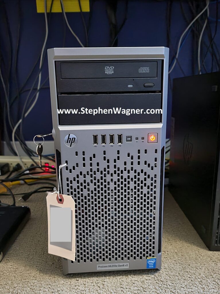
  3. HPE ML310e Gen8 v2 (Single Proc, 32GB RAM)

For the DL360p servers, while the servers are beefy enough, have enough power (dual redundant power supplies), and resources, unfortunately the PCIe slots are half-height. In order for me to use a dual-height card, I’d need to rig something up to have an eGPU (external GPU) outside of the server.

As for the ML310e, it’s an entry level tower server. While it does support dual-height (dual slot) PCIe cards, it only has a single 350W power supply, misses some fancy server technologies (I’ve had issues with VT-d, etc), and only a single processor. I should be able to install the card, however I’m worried about powering it (it has no 6pin PCIe power connector), and having ESXi be able to use it.

Finally, I was worried about cooling. The GRID K1 and GRID K2 are typically passively cooled and meant to be installed in to rack servers with fans running at jet engine speeds. If I used the DL360p with an external setup, this would cause issues. If I used the ML310e internally, I had significant doubts that cooling would be enough. The ML310e did have the plastic air baffles, but only had one fan for the expansion cards area, and of course not all the air would pass through the GRID K1 card.

The Purchase

Because of a limited budget, and the possibility I may not even be able to get it working, I didn’t want to spend too much. I found an eBay user local in my city who had a couple Grid K1 and Grid K2 cards, as well as a bunch of other cool stuff.

We spoke and he decided to give me a wicked deal on the Grid K1 card. I thought this was a fantastic idea as the power requirements were significantly less (more likely to work on the ML310e) on the K1 card at 130 W max power, versus the K2 card at 225 W max power.

NVIDIA GRID K1 and K2 Specifications
NVIDIA GRID K1 and K2 Specification Table

The above chart is a capture from:
https://www.nvidia.com/content/cloud-computing/pdf/nvidia-grid-datasheet-k1-k2.pdf

We set a time and a place to meet. Preemptively I ran out to a local supply store to purchase an LP4 power adapter splitter, as well as a LP4 to 6pin PCIe power adapter. There were no available power connectors inside of the ML310e server so this was needed. I still thought the chances of this working were slim…

These are the adapters I purchased:

Preparation and Software Installation

I also decided to go ahead and download the Nvidia GRID Software Package. This includes the release notes, user guide, ESXi vib driver (includes vSGA, vGPU), as well as guest drivers for vGPU and pass through. The package also includes the GRID vGPU Manager. The driver I used was from:
https://www.nvidia.com/Download/driverResults.aspx/144909/en-us

To install, I copied over the vib file “NVIDIA-vGPU-kepler-VMware_ESXi_6.5_Host_Driver_367.130-1OEM.650.0.0.4598673.vib” to a datastore, enabled SSH, and then ran the following command to install:

esxcli software vib install -v /path/to/file/NVIDIA-vGPU-kepler-VMware_ESXi_6.5_Host_Driver_367.130-1OEM.650.0.0.4598673.vib

The command completed successfully and I shut down the host. Now I waited to meet.

We finally met and the transaction went smooth in a parking lot (people were staring at us as I handed him cash, and he handed me a big brick of something folded inside of grey static wrap). The card looked like it was in beautiful shape, and we had a good but brief chat. I’ll definitely be purchasing some more hardware from him.

Hardware Installation

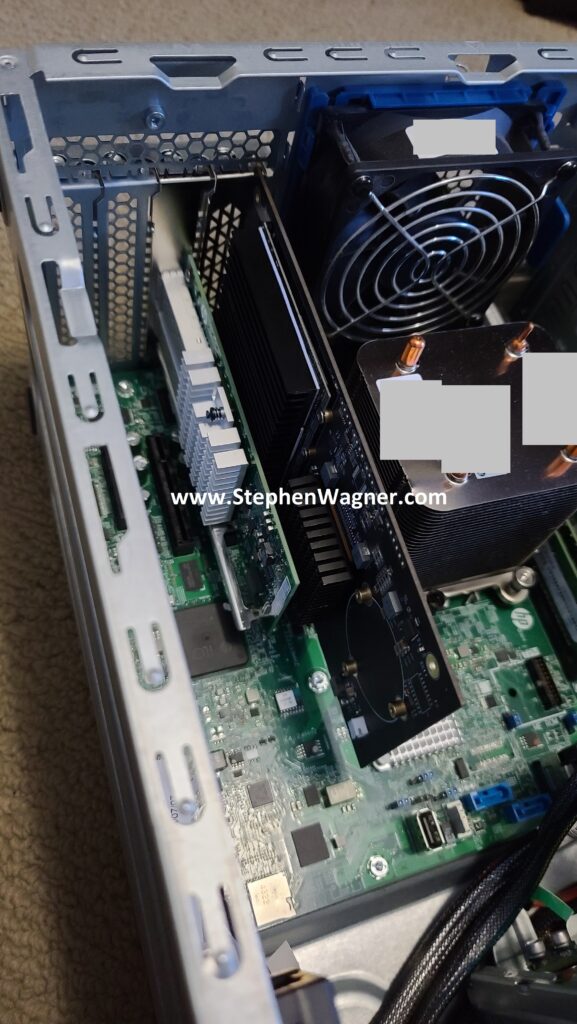
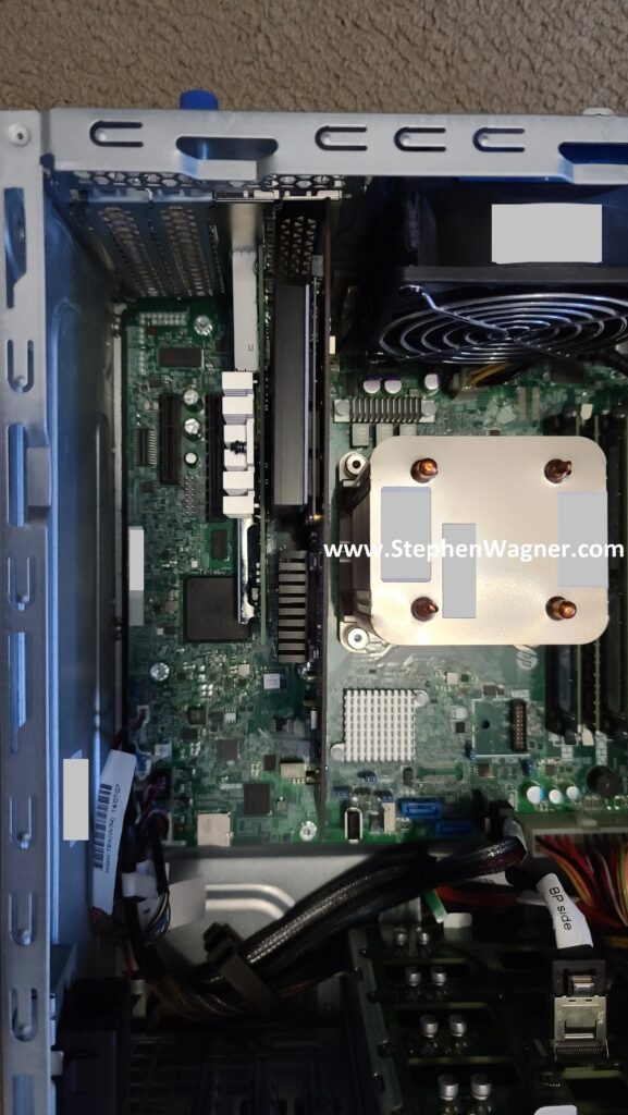
Installing the card in the ML310e was difficult and took some time with care. First I had to remove the plastic air baffle. Then I had issues getting it inside of the case as the back bracket was 1cm too long to be able to put the card in. I had to finesse and slide in on and angle but finally got it installed. The back bracket (front side of case) on the other side slid in to the blue plastic case bracket. This was nice as the ML310e was designed for extremely long PCIe expansion cards and has a bracket on the front side of the case to help support and hold the card up as well.

For power I disconnected the DVD-ROM (who uses those anyways, right?), and connected the LP5 splitter and the LP5 to 6pin power adapter. I finally hooked it up to the card.

I laid the cables out nicely and then re-installed the air baffle. Everything was snug and tight.

Please see below for pictures of the Nvidia GRID K1 installed in the ML310e Gen8 V2.

Host Configuration

Powering on the server was a tense moment for me. A few things could have happened:

  1. Server won’t power on
  2. Server would power on but hang & report health alert
  3. Nvidia GRID card could overheat
  4. Nvidia GRID card could overheat and become damaged
  5. Nvidia GRID card could overheat and catch fire
  6. Server would boot but not recognize the card
  7. Server would boot, recognize the card, but not work
  8. Server would boot, recognize the card, and work

With great suspense, the server powered on as per normal. No errors or health alerts were presented.

I logged in to iLo on the server, and watched the server perform a BIOS POST, and start it’s boot to ESXi. Everything was looking well and normal.

After ESXi booted, and the server came online in vCenter. I went to the server and confirmed the GRID K1 was detected. I went ahead and configured 2 GPUs for vGPU, and 2 GPUs for 3D vSGA.

ESXi Graphics Settings for Host Graphics and Graphics Devices
ESXi Host Graphics Devices Settings

VM Configuration

I restarted the X.org service (required when changing the options above), and proceeded to add a vGPU to a virtual machine I already had configured and was using for VDI. You do this by adding a “Shared PCI Device”, selecting “NVIDIA GRID vGPU”, and I chose to use the highest profile available on the K1 card called “grid_k180q”.

Virtual Machine Edit Settings with NVIDIA GRID vGPU and grid_k180q profile selected
VM Settings to add NVIDIA GRID vGPU

After adding and selecting ok, you should see a warning telling you that must allocate and reserve all resources for the virtual machine, click “ok” and continue.

Power On and Testing

I went ahead and powered on the VM. I used the vSphere VM console to install the Nvidia GRID driver package (included in the driver ZIP file downloaded earlier) on the guest. I then restarted the guest.

After restarting, I logged in via Horizon, and could instantly tell it was working. Next step was to disable the VMware vSGA Display Adapter in the “Device Manager” and restart the host again.

Upon restarting again, to see if I had full 3D acceleration, I opened DirectX diagnostics by clicking on “Start” -> “Run” -> “dxdiag”.

DirectX Diagnostic Tool (dxdiag) showing Nvidia Grid K1 on VMware Horizon using vGPU k180q profile
dxdiag on GRID K1 using k180q profile

It worked! Now it was time to check the temperature of the card to make sure nothing was overheating. I enabled SSH on the ESXi host, logged in, and ran the “nvidia-smi” command.

nvidia-smi command on ESXi host showing GRID K1 information, vGPU information, temperatures, and power usage
“nvidia-smi” command on ESXi Host

According to this, the different GPUs ranged from 33C to 50C which was PERFECT! Further testing under stress, and I haven’t gotten a core to go above 56. The ML310e still has an option in the BIOS to increase fan speed, which I may test in the future if the temps get higher.

With “nvidia-smi” you can see the 4 GPUs, power usage, temperatures, memory usage, GPU utilization, and processes. This is the main GPU manager for the card. There are some other flags you can use for relevant information.

nvidia-smi with vgpu flag for vgpu information
“nvidia-smi vgpu” for vGPU Information
nvidia-smi with vgpu -q flag
“nvidia-smi vgpu -q” to Query more vGPU Information

Final Thoughts

Overall I’m very impressed, and it’s working great. While I haven’t tested any games, it’s working perfect for videos, music, YouTube, and multi-monitor support on my 10ZiG 5948qv. I’m using 2 displays with both running at 1920×1080 for resolution.

I’m looking forward to doing some tests with this VM while continuing to use vGPU. I will also be doing some testing utilizing 3D Accelerated vSGA.

The two coolest parts of this project are:

  • 3D Acceleration and Hardware h.264 Encoding on VMware Horizon
  • Getting a GRID K1 working on an HPE ML310e Gen8 v2

Highly recommend getting a setup like this for your own homelab!

Uses and Projects

Well, I’m writing this “Uses and Projects” section after I wrote the original article (it’s now March 8th, 2020). I have to say I couldn’t be impressed more with this setup, using it as my daily driver.

Since I’ve set this up, I’ve used it remotely while on airplanes, working while travelling, even for video editing.

Some of the projects (and posts) I’ve done, can be found here:

Leave a comment and let me know what you think! Or leave a question!

Feb 182019
 
ESXi Fatal error: 8 (Device Error)

Unable to boot ESXi from USB or SD Card on HPE Proliant Server

After installing HPE iLO Amplifier on your network and updating iLO 4 firmware to 2.60 or 2.61, you may notice that your HPE Proliant Servers may fail to boot ESXi from a USB drive or SD-Card.

This was occuring on 2 ESXi Hosts. Both were HPE Proliant DL360p Gen8 Servers. One server was using an internal USB drive for ESXi, while the other was using an HPE branded SD Card.

The issue started occuring on both hosts after a planned InfoSight implementation. Both hosts iLO controllers firmware were upgraded to 2.61, iLO Amplifier was deployed (and the servers added), and the amplifier was connected to an HPE InfoSight account.

Update – May 24th 2019: As an HPE partner, I have been working with HPE, the product manager, and development team on this issue. HPE has provided me with a fix to test that I have been able to verify fully resolves this issue! Stay tuned for more information!

Update – June 5th 2019: Great news! As Bob Perugini (WW Product Manager at HPE) put it: “HPE is happy to announce that this issue has been fixed in latest version of iLO Amplifier Pack, v1.40. To download iLO Amplifier Pack v1.40, go to http://www.hpe.com/servers/iloamplifierpack and click “download”.” Scroll to the bottom of the post for more information!

Please see below for errors:

Errors

ESXi Fatal error: 8 (Device Error)
Error loading /s.v00
Compressed MD5: 00000000000000000000000000
Decompressed MD5: 00000000000000000000000000
Fatal error: 8 (Device Error)
Error mboot.c32 attempted DOS system call
mboot.c32: attempted DOS system call INT 21 0d00 E8004391
boot:

Symptoms

This issue may occur intermittently, on the majority of boots, or on all boots. Re-installing ESXi on the media, as well as replacing the USB/SD Card has no effect. Installation will be successful, however you the issue is still experiences on boot.

HPE technical support was unable to determine the root of the issue. We found the source of the issue and reported it to HPE technical support and are waiting for an update.

The Issue and Fix

This issue occurs because the HPE iLO Amplifier is running continuous server inventory scans while the hosts are booting. When one inventory completes, it restarts another scan.

The following can be noted:

  • iLO Amplifier inventory percentage resets back to 0% and starts again numerous times during the server boot
  • Inventory scan completes, only to restart again numerous times during the server boot
  • Inventory scan resets back to 0% during numerous different phases of BIOS initialization and POST.
HPe iLO Amplifier Inventory
HPE iLO Amplifier Inventory

We noticed that once the HPE iLO Amplifier Virtual Machine was powered off, not only did the servers boot faster, but they also booted 100% succesfully each time. Powering on the iLO Amplifier would cause the ESXi hosts to fail to boot once again.

I’d also like to note that on the host using the SD-Card, the failed boot would actually completely lock up iLO, and would require physical intervention to disconnect and reconnect the power to the server. We were unable to restart the server once it froze (this did not happen to the host using the USB drive).

There are some settings on the HPE iLO amplifier to control performance and intervals of inventory scans, however we noticed that modifying these settings did not alter or stop the issue, and had no effect.

As a temporary workaround, make sure your iLO amplifier is powered off during any maintenance to avoid hosts freezing/failing to boot.

To fully resolve this issue, upgrade your iLO Amplifier to the latest version (1.40 as of the time of this update). The latest version can be downloaded at: http://www.hpe.com/servers/iloamplifierpack.

Update – April 10th 2019

I’ve attempted to try downgrading to the earliest supported iLo version 2.54, and the issue still occurs.

I also upgraded to the newest version 2.62 which presented some new issues.

On the first boot, the BIOS reported memory access issues on Processor 1 socket 1, then another error reporting memory access issues on Processor 1 socket 4.

I disconnected the power cables, reconnected, and restarted the server. This boot, the server didn’t even detect the bootable USB stick.

Again, after shutting down the iLo Amplifier, the server booted properly and the issue disappeared.

Update – May 24th 2019

As an HPE partner, I have been working with HPE, the product manager, and development team on this issue. HPE has provided me with a fix to test that I have been able to verify fully resolves this issue! Stay tuned for more information!

Update – June 5th 2019 – ITS FIXED!!!

Great news as the issue is now fixed! As Bob Perugini (WorldWide Product Manager at HPE) said it:

HPE is happy to announce that this issue has been fixed in latest version of iLO Amplifier Pack, v1.40.

To download iLO Amplifier Pack v1.40, go to http://www.hpe.com/servers/iloamplifierpack and click “download”.


Here’s what’s new in iLO Amplifier Pack v1.40:
─ Available as a VMware ESXi appliance and as a Hyper-V appliance (Hyper-V is new)
─ VMware tools have been added to the ESXi appliance
─ Ability to schedule the time of the daily transmission of Active Health System (AHS) data to InfoSight
─ Ability to opt-in and allow the IP address and hostname of the server to be transmitted to InfoSight and displayed
─ Test connectivity button to help verify iLO Amplifier Pack has successfully connected to InfoSight
─ Allow user authentication credentials for the proxy server when connecting to InfoSight
─ Added ability to specify IP address or hostname for the HPE RDA connection when connection to InfoSight
─ Ability to send updated AHS data “now” for an individual server
─ Ability to stage firmware and driver updates to the iLO Repository and then deploy the staged updates at a later date or time (HPE Gen10 servers only)
─ Allow the firmware and driver updates of servers whose iLO has been configured in CNSA (Commercial National Security Algorithm) mode (HPE Gen10 servers only)

Nov 042018
 

This weekend I came across a big issue with my HPE MSA 2040 where one of the SAN controllers became unresponsive, and appeared to had failed because it would not boot.

It all started when I decided to clean the MSA SAN. I try to clean the components once or twice a year to remove dust and make sure it’s not getting all jammed up. Sometimes I’ll shut the entire unit down and remove the individual components, other times I’ll remove them while operating. Because of the redundancies and since I have two controllers, I can remove and clean each controller individually at separate times.

Please Note: When dusting equipment with fans, never allow the fans to spin up with compressed air as this can generate current which can damage components. Never allow compressed air flow to spin up fans.

After cleaning out the power supplies, it came time to clean the controllers.

The Problem

As always, I logged in to the SMU to shutdown controller A (storage). I shut it down, the blue LED illuminated it was safe for removal. I then proceeded to remove it, clean it, and re-insert it. The controller came back online, and ownership of the applicable disk groups were successfully moved back. Controller A was now completed successfully. I continued to do the same for controller B: I logged in to shutdown controller B (storage). It shut down just like controller A, the blue LED removable light illuminated. I was able to remove it, clean it, and re-insert it.

However, controller B did not come back online.

After inserting controller B, the status light was flashing (as if it was booting). I waited 20 minutes with no change. The SMU on controller B was responding to HTTPS requests, however you could not log on due to the error “system is initializing”. SSH was functioning and you could log in and issue commands, however any command to get information would return “Please wait while this information is pulled from the MC controller”, and ultimately fail. The SMU on controller A would report a controller fault on controller B, and not provide any other information (including port status on controller B).

I then tried to re-seat the controller with the array still running. Gave it plenty of time with no effect.

I then removed the failed controller, shutdown the unit, powered it back on (only with controller A), and re-inserted Controller B. Again, no effect.

The Fix

At this point I’m thinking the controller may have failed or died during the cleaning process. I was just about to call HPE support for a replacement until I noticed the “Power LED” light inside of the failed controller would flash every 5 seconds while removed.

This made me start to wonder if there was an issue writing the cache to the compact flash card, or if the controller was still running off battery power but had completely frozen.

I tried these 3 things on the failed controller while it was unplugged and removed:

  1. I left the controller untouched for 1 hour out of the array (to maybe let it finish whatever it was doing while on battery power)
  2. There’s an unlabeled button on the back of the controller. As a last resort (thinking it was a reset button), I pressed and held it for 20 seconds, waited a minute, then briefly pressed it for 1 second while it was out of the unit.
  3. I removed the Compact Flash card from the controller for 1 minute, then re-inserted it. In hoping this would fail the cache copy if it was stuck in the process of writing cache to compact flash.

I then re-inserted the controller, and it booted fine! It was not functioning and working (and came up very fast). Looking at the logs, it has no record of what occurred between the first shutdown, and final boot. I hope this post helps someone else with the same issue, it can save you a support ticket, and time with a controller down.

Disclaimer

PLEASE NOTE: I could not find any information on the unlabeled button on the controller, and it’s hard to know exactly what it does. Perform this at your own risk (make sure you have a backup). Since I have 2 controllers, and my MSA 2040 was running fine on Controller A, I felt comfortable doing this, as if this did reset controller B, the configuration would replicate back from controller A. I would not do this in a single controller environment.

Update – 24 Hours later

After I got everything up and running, I checked the logs of the unit and couldn’t find anything on controller B that looked out of ordinary. However, 24 hours later, I logged back in and noticed some new events showed up from the day before (from the day I had the issues):

MSA 2040 Code 549
MSA 2040 Code 549

You’ll notice the event log with severity error:

Recovery from internal processor fault detected on controller.
Code 549

One thing that’s very odd is that I know for a fact the time is wrong on the error severity log entry, this could be due to the fact we had a daylight savings time change last night at midnight. Either way it appears that it finally did detect that the Storage controller was in an error state and logged it, but it still would have been nice for some more information.

On a final note, the unit has been running perfectly for over 24 hours.

Update – April 2nd 2019

Well, in March a new firmware update was released for the MSA. I went to upgrade and the same issue as above occurred. During the firmware upgrade, at one point of the firmware update process a step had failed and repeated 4 times until successful.

The firmware update log (below was repeated):

Updating system configuration files
System configuration complete
Loading SC firmware.
STATUS: Updating Storage Controller firmware.
Waiting 5 seconds for SC to shutdown.
Shutdown of SC successful.
Sending new firmware to SC.
Updating SC Image:Remaining size 6263505
Updating SC Image:Remaining size 5935825
Updating SC Image:Remaining size 5608145
Updating SC Image:Remaining size 5280465
Updating SC Image:Remaining size 4952785
Updating SC Image:Remaining size 4625105
Updating SC Image:Remaining size 4297425
Updating SC Image:Remaining size 3969745
Updating SC Image:Remaining size 3642065
Updating SC Image:Remaining size 3314385
Updating SC Image:Remaining size 2986705
Updating SC Image:Remaining size 2659025
Updating SC Image:Remaining size 2331345
Updating SC Image:Remaining size 2003665
Updating SC Image:Remaining size 1675985
Updating SC Image:Remaining size 1348305
Updating SC Image:Remaining size 1020625
Updating SC Image:Remaining size 692945
Updating SC Image:Remaining size 365265
Updating SC Image:Remaining size 37585
Waiting for Storage Controller to complete programming.
Please wait...
Please wait...
Please wait...
Please wait...
Storage Controller has completed programming.
Got an error (138) on firmware packet
CAPI error: Firmware Update failed. Controller needs to reboot.
Waiting 5 seconds for SC to shutdown.
Shutdown of SC successful.
Sending new firmware to SC.
Updating SC Image:Remaining size 6263505
Updating SC Image:Remaining size 5935825
Updating SC Image:Remaining size 5608145
Updating SC Image:Remaining size 5280465
Updating SC Image:Remaining size 4952785
Updating SC Image:Remaining size 4625105
Updating SC Image:Remaining size 4297425
Updating SC Image:Remaining size 3969745
Updating SC Image:Remaining size 3642065
Updating SC Image:Remaining size 3314385
Updating SC Image:Remaining size 2986705
Updating SC Image:Remaining size 2659025
Updating SC Image:Remaining size 2331345
Updating SC Image:Remaining size 2003665
Updating SC Image:Remaining size 1675985
Updating SC Image:Remaining size 1348305
Updating SC Image:Remaining size 1020625
Updating SC Image:Remaining size 692945
Updating SC Image:Remaining size 365265
Updating SC Image:Remaining size 37585
Waiting for Storage Controller to complete programming.
Please wait...
Please wait...
Storage Controller has completed programming.
Updating SC Image:Remaining size 0
Storage Controller has been successfully updated.
STATUS: Current CPLD firmware is up-to-date.
CPLD update not required.
==========================================
Software Component Load Summary:
MC Software:    SUCCESSFUL
SC Software:    SUCCESSFUL
EC Software:    NOT ATTEMPTED
CPLD Software:  NOT ATTEMPTED
==========================================

During the Storage Controller restarting process, the controller never came back up. I removed the controller 1 hour, re-inserted and the above fix did not work. I then tried it after 2 hours of disconnection.

At this point I contacted HPE, who is sending a replacement controller.

The following day (12 hours of controller removed), I re-inserted it again and it actually booted up, was working with the new firmware, and then did a PFU (Partner Firmware Update) of controller A.

While it is working now, I’m still going to replace the controller as I believe something is not functioning correctly.

Aug 272018
 
Right side of MSA 2040

So, what happens in a worst-case scenario where your backup system fails, you don’t have any VM snapshots, and the last thing standing in the way of complete data loss is your SAN storage systems LUN snapshots?

Well, first you fire whoever purchased and implemented the backup system, then secondly you need to start restoring the VM (or VMs) from your SAN LUN snapshots.

While I’ve never had to do this in the past (all the disaster recovery solutions I’ve designed and sold have been tested and function), I’ve always been curious what the process is and would be like. Today I decided to try it out and develop a procedure for restoring a VM from SAN Storage LUN snapshot.

For this test I pretended a VM was corrupt on my VMware vSphere cluster and then restored it to a previous state from a LUN snapshot on my HPE MSA 2040 (identical for the HPE MSA 2050, and MSA 2052) Dual Controller SAN.

To accomplish the restore, we’ll need to create a host mapping on the SAN for the LUN snapshot to a new LUN number available to the hosts. We then need to add and mount the VMFS volume (residing on the snapshot) to the host(s) while assigning it a new signature and then vMotion the VM from the snapshot’s VMFS to original datastore.

Important Notes (Read first):

  • When mounting a VMFS volume from a SAN snapshot, you MUST RE-SIGNATURE THE SNAPSHOT VMFS volume. Not doing so can cause problems.
  • The snapshot cannot be mapped as read only, VMFS volumes must be marked as writable in order to be mounted on ESXi hosts.
  • You must follow the proper procedure to gracefully dismount and detach the VMFS volume and storage device before removing the snapshot’s host mapping on the SAN.
  • We use Storage vMotion to perform a high-speed move and recovery of the VM. If you’re not licensed for Storage vMotion, you can use the datastore file browser and copy/move from the snapshot VMFS volume to live production VMFS volume, however this may be slower.
  • During this entire process you do not touch, modify, or change any settings on your existing active production LUNs (or LUN numbers).
  • Restoring a VM from a SAN LUN snapshot will restore a crash consistent copy of the VM. The VM when recovered will believe a system crash occurred and power was lost. This is NOT a graceful application consistent backup and restore.
  • Please read your SAN documentation for the procedure to access SAN snapshots, and create host mappings. With the MSA 2040 I can do this live during production, however your SAN may be different and your hosts may need to be powered off and disconnected while SAN configuration changes are made.
  • Pro tip: You can also power on and initialize the VM from the snapshot before initiating the storage vMotion. This will allow you to get production services back online while you’re moving the VM from the snapshot to production VMFS volumes.
  • I’m not responsible if you damage, corrupt, or cause any damage or issues to your environment if you follow these procedures.

We are assuming that you have already either deleted the damaged VM, or removed it from your inventory and renamed the VMs folder on the live VMFS datastore to change the name (example, renaming the folder from “SRV01” to “SRV01.bad”. If you renamed the damaged VM, make sure you have enough space for the new restored VM as well.

Procedure:

Mount the VMFS volume on the LUN snapshot to the ESXi host(s)
  1. Identify the VM you want to recover, write it down.
  2. Identify the datastore that the VM resides on, write it down.
  3. Identify the SAN and identify the LUN number that the VMFS datastore resides on, write it down.
  4. Identify the LUN Snapshot unique name/id/number and write it down, confirm the timestamp to make sure it will contain a valid recovery point.
  5. Log on to the SAN and create a host mapping to present the snapshot (you recorded above) to the hosts using a new and unused LUN number.
  6. Log on to your ESXi host and navigate to configuration, then storage adapters.
  7. Select the iSCSI initator and click the “Rescan Storage Adapters” button to rescan all iSCSI LUNs.

    VMware ESXi Host Rescan Storage Adapter

    VMware ESXi Host Rescan Storage Adapter

  8. Ensure both check boxes are checked and hit “Ok”, wait for the scan to complete (as shown in the “Recent Tasks” window.

    VMware ESXi Host Rescan Storage Adapter Window for VMFS Volume and Devices

    VMware ESXi Host Rescan Storage Adapter Window for VMFS Volume and Devices

  9. Now navigate to the “Datastores” tab under configuration, and click on the “Create a new Datastore” button as shown below.

    VMware ESXi Host Add Datastore Window

    VMware ESXi Host Add Datastore Window

  10. Continue with “VMFS” selected and select continue.
  11. In the next window, you’ll see your existing datastores, as well as your new datastore (from the snapshot). You can leave the “Datastore name” as is since this value will be ignored. In this window you’re going to select the new VMFS datastore from the snapshot. Make sure you confirm this by looking at the LUN number, as well as the value under “SnapshotVolume”. It is critical that you select the snapshot in this window (it should be the new LUN number you added above).
  12. Select next and continue.
  13. On the next window “Mount Option”, you need to change the radio button to and select “Assign a new signature”. This is critical! This will assign a new signature to differentiate it from your existing real production datastore so that the ESXi hosts don’t confuse it.
  14. Continue with the wizard and complete the mount process. At this point ESXi will resignture the VMFS volume and rename it to “snap-OriginalVolumeNameHere”.
  15. You can now browse the VMFS datastore residing on the LUN snapshot and do anything you’d normally be able to do with a normal datastore.
Copy/Move/vMotion the VM from the snapshot VMFS volume to your production VMFS volume

Note: The next steps are only if you are licensed for storage vMotion. If you aren’t you’ll need to use the copy or move function in the file browsing area to copy or move the VMs to your live production VMFS datastores:

  1. Now we’ll go to the vCenter/ESXi host storage area in the web client, and using the “Files” tab, we’ll browse the snapshots VMFS datastore that we just mounted.
  2. Locate the folder for the VM(s) you want to recover, open the folder, right click on the vmx file for the VM and select “Register VM”. Repeat this for any of the VMs you want to recover from the snapshot. Complete the wizard for each VM you register and add it to a host.
  3. Go back to you “Hosts and VMs” view, you’ll now see the VMs are added.
  4. Select and right click on the VM you want to move from the snapshot datastore to your production live datastore, and select “Migrate”.
  5. In the vMotion migrate wizard, select “Change Storage only”.
  6. Continue to the wizard, and storage vMotion the VM from the snapshot VMFS to your production VMFS volume. Wait for the vMotion to complete.
  7. After the storage vMotion is complete, boot the VM and confirm everything is functioning.
Gracefully unmount, detach, and remove the snapshot VMFS from the ESXi host, and then remove the host mapping from the SAN
  1. On each of your ESXi hosts that have access to the SAN, go to the “Datastores” section under the ESXi hosts configuration, right click on the snapshot VMFS datastore, and select “Unmount”. You’ll need to repeat this on each ESXi host that may have automounted the snapshot’s VMFS volume.
  2. On each of your ESXi hosts that have access to the SAN, go to the “Storage Devices” section under the ESXi hosts configuration and identify (by LUN number) the “disk” that is the snapshot LUN. Select and highlight the snapshot LUN disk, select “All Actions” and select “Detach”. Repeat this on each host.
  3. Double check and confirm that the snapshot VMFS datastore (and disk object) have been unmounted and detached from each ESXi host.
  4. You can now log in to your SAN and remove the host mapping for the snapshot-to-LUN. We will not longer present the snapshot LUN to any of the hosts.
  5. Back to the ESXi hosts, navigate to “Storage Adapters”, select the “iSCSI Initiator Adapter”, and click the “Rescan Storage Adapters”. Repeat this for each ESXi host.

    VMware ESXi Host Rescan Storage Adapter

    VMware ESXi Host Rescan Storage Adapter

  6. You’re done!
Aug 222018
 

HPE Moonshot

I had the pleasure of playing with a fully loaded HPE Moonshot 1500 Chassis, and an HPe Edgeline EL4000 Converged Edge System last month during my visit to HPe Headquarters in Toronto, Ontario. I like to think of this thing as the answer for high-density anything and everything!

HPE Moonshot 1500 Chassis

I’ve known about the HPE Moonshot portfolio for some time, however I didn’t understand how mammoth one of these chassis’ are until I saw it performing in real life.

HPe Moonshot 1500 Chassis with 45 Cartridges

HPE Moonshot 1500 Chassis with 45 Cartridges

The HPE Moonshot 1500 Chassis supports up to 45 cartridges, and up to 4 SoC (System on Chip) OS instances per cartridge for a total of 180 OS instances in a 4.3U (5U for 1 x 1500 Chassis or 13U for 3 x 1500 Chassis) sized footprint. The chassis also supports up to 2 switches and 2 uplink modules in addition to the 45 cartridges.

Prime uses for HPE Moonshot 1500 (remember, high-density everything):

  • VDI (Virtual Desktop Infrastructure via VMware or Microsoft)
  • HDI (Hosted Desktop Infrastructure via Citrix Provisioning Server)
  • Server consolidation and Virtualization
  • SDDC (Software Defined Data Center)
  • HPC (High Performance Computing, both Virtualized and Non-Virtualized workloads)
  • Energy Efficient Compute
  • EUC (End User Computing – Software defined end user desktops without virtualization)
  • Video Transcoding
  • Analytics and Interpritation
  • IoT and AI
  • Custom workloads

As you can see, you can virtually load up whatever you’d like on it that requires a CPU (HPE Moonshot can run both x86 and ARM architectures depending on which cartridges are utilized).

The chassis is monitored and managed via the HPE Moonshot 1500 Chassis Management module and the HPE Moonshot Provisioning Manager.

HPE Edgeline EL4000 Converged Edge System

The HPE Edgeline EL4000 was designed (you probably guessed it) for the edge. Whether it be the enterprise edge, media edge, or IoT edge, the EL4000 is a perfect fit.

HPe Edgeline EL4000 Converged Edge System

HPE Edgeline EL4000 Converged Edge System

This bad boy supports up to 4 HPE Proliant Server Cartridge (m510 or m710x) compute nodes in a 1U package. It also supports up to 4 PCIe cards, or 4 PXIe modules assignable to any of the compute modules.

Prime uses for the HPE Edgeline EL4000:

  • Edge Computing (AI, IoT EDGE)
  • ROBO (Remote Office Branch Office)
  • Server Consolidation and Virtualization (ROBO)
  • VDI (Virtual Desktop Infrastructure)
  • HDI (Hosted Desktop Infrastructure)
  • Video Transcoding
  • Industrial applications (Machine monitoring, Condition Monitoring)
  • Edgeline data analytics
  • Industrial/Manufacturing Quality Control and Quality Assurance (Video Analytics and Interpretation)
  • SMB Applications

The El4000 has iLo (Integrated Lights Out) built in, and provides management and monitoring. This unit also supports GPU accelerator/compute cards such as the Nvidia P4 Graphics Accelerator (specifically an Nvidia Tesla P4 8GB Computational PCIe card).

HPE Moonshot Cartridges

With the flexibility of different cartridges, along with Moonshot being software defined, you can highly customize whatever workload you may be running.

HPe Proliant m800 Moonshot Cartridge Front View

HPE Proliant m800 Moonshot Cartridge Front View

HPe Proliant m800 Moonshot Cartridge Side View

HPE Proliant m800 Moonshot Cartridge Side View

The following cartridges are currently available for the HPE Moonshot platform:

  • HPE Proliant m710p – Server or Desktop Virtualization, includes Intel Iris Pro P6300 graphics for VDI deployments (supported by VMware vSphere for vDGA passthrough and vSGA) or video transcoding.
  • HPE Proliant m710x – Server or Desktop Virtualization, includes Intel Iris Pro P580 graphics for VDI deployments (supported by VMware vSphere for vDGA passthrough and vSGA) or video transcoding.
  • HPE Proliant m700p – Designed for high-performance Citrix Mobile Workspaces (high-density EUC) for 4 desktops per cartridge with AMD Radeon HD 8000 graphics.
  • HPE Proliant m510 – Features the Xeon D processor targeting high performance, AI, analytics, machine learning, and IoT workloads.

As you can see there is quite some flexibility as far as the cartridges you can roll out. I get really excited when I think of VDI with Moonshot just because of the fact that the Intel Iris Pro P580, and P6300 are fully supported on VMware’s HCL for vDGA and vSGA graphics for vSphere 6.5 and 6.7.

There are also retired/discontinued cartridges (such as the HPE Proliant m800) which are beyond the scope of this blog post.

HPE Moonshot Networking

On the HPe Moonshot 1500 Chassis, networking is handled inside of the chassis via 1 or 2 network switch modules and uplink modules. You’ll then connect the uplinks from the uplink modules to your real physical network. You can connect to your network via QSFP+ or SFP+ connections using DAC (direct attached cables) or fiber cables with transceivers at speeds of 40Gb or 10Gb.

The Moonshot 1500 chassis supports the following switch modules:

  • Moonshot-45Gc Switch – 1Gb Switch connectivity for m510, m510-16c, m710x cartridges and works with the Moonshot 6 x SFP+ Uplink Module
  • Moonshot-45XGc Switch – 1Gb or 10Gb Switch connectivity for m510, m510-16c, m710x cartridges and works with the Moonshot 16 x SFP+ Uplink Module or the 4 QSFP+ Uplink Module
  • Moonshot-180XGc Switch – 1Gb or 10Gb Switch connectivity for m510, m510-16c, m710x cartridges, and 1Gb Switch connectivity for m700p and works with the Moonshot 16 x SFP+ Uplink Module or the 4 QSFP+ Uplink Module

On the HPE Edgeline EL4000, networking is handled via 2 x 10Gb SFP+ switched version, or a 8 x 10Gb QSFP+ pass-thru version. The unit also has a dedicated 1Gb RJ45 port for HPE iLo connectivity.

HPE Moonshot Storage

Each cartridge can contain it’s own dedicated storage up to 2TB. This is perfect for a HPE StoreVirtual VSA deployment or even basic direct attached storage. You can also connect HPE Moonshot to an HPE 3PAR SAN or an HPE Apollo 4500 storage system via the 10Gb network Fabric.

There’s a few options as to how you can plan your storage deployment with Moonshot:

  • DAS – Direct Attached Storage (in cartridge)
  • HPE 3PAR SAN or HPE Apollo 4500 Storage System
  • iSCSI/NFS (May or may not be supported depending on your workload)
  • VMware vSAN (May or may not be supported/certified)

As you can see, there’s quite a few options and possibilities as far as your storage deployment goes.

HPE Moonshot Pictures

Here’s some additional photos of the unit.

HPe Moonshot at HPe Center of Excellence

HPE Moonshot 1500 Chassis opened and running

HPe Moonshot 1500 Chassis with Cartridges

HPE Moonshot 1500 Chassis with Cartridges

And remember, if you’re interested in the HPE Moonshot product or any other products or solutions in HPE’s portfolio, please don’t hesitate to reach out to me or my company (Digitally Accurate Inc.) for more information as we are an HPE partner and design/configure/sell HPE solutions!

Apr 172018
 

With the news of VMware vSphere 6.7 being released today, a lot of you are looking for the download links for the 6.7 download (including vSphere 6.7, ESXi 6.7, etc…). I couldn’t find it myself, but after doing some scouring through alternative URLs, I came across the link.

VMware vSphere 6.7 DownloadVMware vSphere 6.7 Download Link

Here’s the link: https://my.vmware.com/web/vmware/info/slug/datacenter_cloud_infrastructure/vmware_vsphere/6_7

HPE Specific (HPE Customization for ESXi) Version 6.7 is available at: https://www.hpe.com/us/en/servers/hpe-esxi.html

Unfortunately the page is blank at the moment, however you can bet the download and product listing will be added shortly!

UPDATE 10:15AM MST: The Download link is now live!

More information on the release of vSphere 6.7 can be found here, here, here, here, here, and here.

An article on the upgrade can be found at: https://blogs.vmware.com/vsphere/2018/05/upgrading-vcenter-server-appliance-6-5-6-7.html

Happy Virtualizing!