This month on June 23rd, HPE is hosting their annual HPE Discover event. This year is a little bit different as COVID-19 has resulted in a change of the usual in-person event, and this year’s event is now being hosted as a virtual experience.
I expect it’ll be the same great content as they have every year, only difference is you’ll be able to virtually experience it from the comfort of your own home.
I’m especially excited to say that I’ve been invited to be special VIP Influencer for the event, so I’ll be posting some content on Twitter, LinkedIn, and of course generating some posts on my blog.
Looking at using SSD and NVMe with your FreeNAS or TrueNAS setup and ZFS? There’s considerations and optimizations that must be factored in to make sure you’re not wasting all that sweet performance. In this post I’ll be providing you with my own FreeNAS and TrueNAS ZFS optimizations for SSD and NVMe to create an NVMe Storage Server.
This post will contain observations and tweaks I’ve discovered during testing and production of a FreeNAS ZFS pool sitting on NVMe vdevs, which I have since upgraded to TrueNAS Core. I will update it with more information as I use and test the array more.
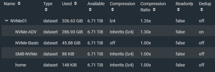
FreeNAS/TrueNAS ZFS NVMe SSD Pool with multiple datasets
Considerations
It’s important to note that while your SSD and/or NVMe ZFS pool technically could reach insane speeds, you will probably always be limited by the network access speeds.
With this in mind, to optimize your ZFS SSD and/or NVMe pool, you may be trading off features and functionality to max out your drives. These optimizations may in fact be wasted if you reach the network speed bottleneck.
Some feature you may be giving up may actually help extend the life or endurance of your SSD such as compression and deduplication, as they reduce the number of writes performed on each of your vdevs (drives).
You may wish to skip these optimizations should your network be the limiting factor, which will allow you to utilize these features with no performance or minimal performance degradation to the final client. You should measure your network throughput to establish the baseline of your network bottleneck.
Deploying SSD and NVMe with FreeNAS or TrueNAS
For reference, the environment I deployed FreeNAS with NVMe SSD consists of:
1 x FreeNAS instance running as VM with PCI passthrough to NVMe
10Gb networking between DL360 Servers and network
1Gb network between ML310 and network
Update (May 1st, 2021): Since this blog post was created, I have since used what was learned in my new NVMe Storage Server Project. Make sure you check it out after reading this post!
As mentioned above, FreeNAS is virtualizatized on one of the HPE DL360 Proliant servers and has 8 CPUs and 32GB of RAM. The NVME are provided by VMware ESXi as PCI passthrough devices. There has been no issues with stability in the months I’ve had this solution deployed. It is also still working amazing since upgrading FreeNAS to TrueNAS core.
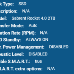
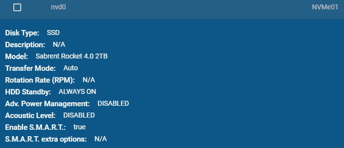
Sabrent Rocket 4 2TB NVMe SSD on FreeNAS
Important notes:
VMXNET3 NIC is used on VMs to achieve 10Gb networking
Using PCI passthrough, snapshots on FreeNAS VM are disabled (this is fine)
NFS VM datastore is used for testing as the host running the FreeNAS VM has the NFS datastore store mounted on itself.
There are a number of considerations that must be factored in when virtualization FreeNAS and TrueNAS however those are beyond the scope of this blog post. I will be creating a separate post for this in the future.
Use Case (Fast and Risky or Slow and Secure)
The use case of your setup will depict which optimizations you can use as some of the optimizations in this post will increase the risk of data loss (such as disabled sync writes and RAIDz levels).
Fast and Risky
Since SSDs are more reliable and less likely to fail, if you’re using the SSD storage as temporary hot storage, you could simply using striping to stripe across multiple vdevs (devices). If a failure occurred, the data would be lost, however if you’re were just using this for “staging” or using hot data and the risk was acceptable, this is an option to drastically increase speeds.
Example use case for fast and risky
VDI Pool for clones
VMs that can be restored easily from snapshots
Video Editing
Temporary high speed data dump storage
The risk can be lowered by replicating the pool or dataset to slower storage on a frequent or regular basis.
Slow and Secure
Using RAIDz-1 or higher will allow for vdev (drive) failures, but with each level increase, performance will be lost due to parity calculations.
Example use case for slow and secure
Regular storage for all VMs
Database (SQL)
Exchange
Main storage
Slow and Secure storage is the type of storage found in most applications used for SAN or NAS storage.
SSD Endurance and Lifetime
Solid state drives have a lifetime that’s typically measured in lifetime writes. If you’re storing sensitive data, you should plan ahead to mitigate the risk of failure when the drive reaches it’s full lifetime.
Steps to mitigate failures
Before putting the stripe or RAIDz pool in to production, perform some large bogus writes and stagger the amount of data written on the SSDs individually. While this will reduce the life counter on the SSDs, it’ll help you offset and stagger the lifetime of each drives so they don’t die at the same time.
If using RAIDz-1 or higher, preemptively replace the SSD before the lifetime is hit. Do this well in advance and stagger it to further create a different between the lifetime of each drive.
Decommissioning the drives preemptively and early doesn’t mean you have to throw them away, this is just to secure the data on the ZFS pool. You can can continue to use these drives in other systems with non-critical data, and possibly use the drive well beyond it’s recommended lifetime.
Compression and Deduplication
Using compression and deduplication with ZFS is CPU intensive (and RAM intensive for deduplication).
The CPU usage is negligible when using these features on traditional magnetic storage (traditional magentic platter hard drive storage) because when using traditional hard drives, the drives are the performance bottleneck.
SSD are a total different thing, specifically with NVMe. With storage speeds in the gigabytes per second, CPUs cannot keep up with the deduplication and compression of data being written and become the bottleneck.
I performed a simple test comparing speeds with compression and dedupe with the same VM running CrystalDiskMark on an NFS VMware datastore running over 10Gb networking. The VM was configured with a single drive on a VMware NVME controller.
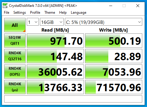
NVMe SSD with compression and deduplication
CrystalDiskMark on FreeNAS NFS SSD datastore with compression and deduplication
NVMe SSD with deduplication only
CrystalDiskMark on FreeNAS NFS SSD datastore with deduplication only
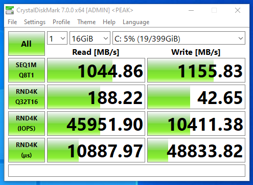
NVMe SSD with compression only
CrystalDiskMark on FreeNAS NFS SSD datastore with compression only
Now this is really interesting, that we actually see a massive speed increase with compression only. This is because I have a server class CPU with multiple cores and a ton of RAM. With lower performing specs, you may notice a decrease in performance.
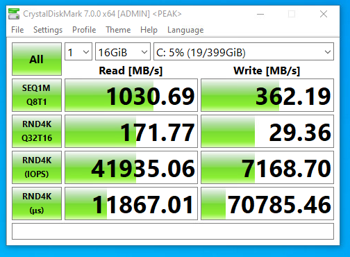
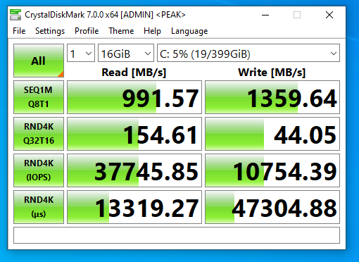
NVMe SSD without compression and deduplication
CrystalDiskMark on FreeNAS NFS SSD datastore without compression and deduplication
In my case, the 10Gb networking was the bottleneck on read operations as there was virtually no change. It was a different story for write operations as you can see there is a drastic change in write speeds. Write speeds are greatly increased when writes aren’t being compressed or deduped.
Note that on faster networks, read speeds could and will be affected.
If your network connection to the client application is the limiting factor and the system can keep up with that bottleneck then you will be able to get away with using these features.
Higher throughput with compression and deduplication can be reached with higher frequency CPUs (more Ghz), more cores (for more client connections). Remember that large amounts of RAM are required for deduplication.
Using compression and deduplication may also reduce the writes to your SSD vdevs, prolonging the lifetime and reducing the cost of maintaining the solution.
ZFS ZIL and SLOG
When it comes to writes on a filesystem, there a different kinds.
Synchronous – Writes that are made to a filesystem that are only marked as completed and successful once it has actually been written to the physical media.
Asynchronous – Writes that are made to a filesystem that are marked as completed or successful before the write has actually been completed and committed to the physical media.
The type of write performed can be requested by the application or service that’s performing the write, or it can be explicitly set on the file system itself. In FreeNAS (in our example) you can override this by setting the “sync” option on the zpool, dataset, or zvol.
Disabling sync will allow writes to be marked as completed before they actually are, essentially “caching” writes in a buffer in memory. See below for “Ram Caching and Sync Writes”. Setting this to “standard” will perform the type of write requested by the client, and setting to “always” will result in all writes being synchronous.
We can speed up and assist writes by using a SLOG for ZIL.
ZIL stands for ZFS Intent Log, and SLOG standards for Separated Log which is usually stored on a dedicated SLOG device.
By utilizing a SLOG for ZIL, you can have dedicated SSDs which will act as your intent log for writes to the zpool. On writes that request a synchronous write, they will be marked as completed when sent to the ZIL and written to the SLOG device.
Implementing a SLOG that is slower than the combined speed of your ZFS pool will result in a performance loss. You SLOG should be faster than the pool it’s acting as a ZIL for.
Implementing a SLOG that is faster than the combined speed of your ZFS pool will result in a performance gain on writes, as it essentially act as “write cache” for synchronous writes and will possibly even perform more orderly writes when it commits it to the actual vdevs in the pool.
If using a SLOG for ZIL, it is highly recommend to use an SSD that has PLP (power loss protection) as well as a mirrored set to avoid data loss and/or corruption in the event of a power loss, crash, or freeze.
RAM Caching and Sync Writes
In the event you do not have a SLOG device to provide a ZIL to your zpool, and you have a substantial amount of memory, you can disable sync writes on the pool which will drastically increase write operations as they will be buffered in RAM memory.
Disabling sync on your zpool, dataset, or zvol, will tell the client application that all writes has been complete and committed to disk (HD or SSD) before it has actually done so. This allows the system to cache writes in the system memory.
In the event of a power loss, crash, or freeze, this data will be lost and/or possibly result in corruption.
You would only want to do this if you had the need for fast storage where data loss would is acceptable (such as video editing, a VDI clone desktop pool, etc).
Utilizing a SLOG for ZIL is much better (and safer) then this method, however I still wanted to provide this for informational purposes as it does apply to some use cases.
SSD Sector Size
Traditional drives typically used 512k physical sector sizes. Newer hard drives and SSDs use 4k sectors, but often emulate 512k logical sectors (called 512e) for compatibility. SSD’s specifically sometimes ship with 512e to increase compatibility with operating systems and the ability to clone your old drive to the new SSD during migrations.
When emulating 512k logical sectors on an HD or SSD that uses 4k physical native sectors, an operation that writes 4k will result in 4 operations instead of 1. This increases overhead and could result in reduced IO and speed, as well as create more wear on the SSD when performing writes.
Some HDs and SSDs come with utilities or tools to change the sector size of the drive. I highly recommend changing it to it’s native sector size.
iSCSI vs NFS
Technically faster speeds should possible using iSCSI instead of NFS, however special care must be made when using iSCSI.
If you’re using iSCSI and the host that is virtualizing the FreeNAS instance is also mounting the iSCSI VMFS target that it’s presenting, you must unmount this iSCSI volume every time you go plan to shut down the FreeNAS instance, or the entire host that is hosting it. Unmounting the iSCSI datastore also means unregistering any VMs that reside on it.
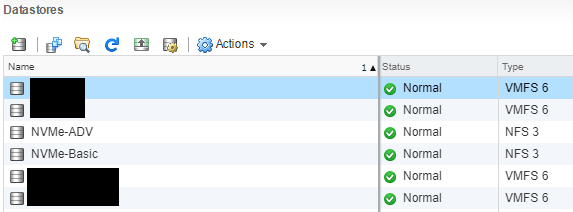
VMware ESXi with virtualized FreeNAS as NFS datastore
If you simply shutdown the FreeNAS instance that’s hosting the iSCSI datastore, this will result in a improper unclean unmount of the VMFS volume and could lead to data loss, even if no VMs are running.
NFS provides a cleaner mechanism, as the FreeNAS handles the unmount of the base filesystem cleanly on shutdown and to the ESXi hosts it appears as an NFS disconnect. If VMs are not running (and no I/O is occuring) when the FreeNAS instance is shut down, data loss is not a concern.
iSCSI MPIO (Multipath I/O)
If your TrueNAS server isn’t virtualized, I’d recommend going with iSCSI because you can configure MPIO (Multipath I/O), which allows redundancy as well as round robin load balancing across multiple connections to the iSCSI target. For example, with 2 x 10Gbe NICs, you should be able to achieve redundancy/failover, as well as 20Gbe combined speeds. If you had 4 x 10Gbe, then you could achieve 40Gbps combined.
Never use LAG or LACP when you want fully optimized NFS, pNFS, or iSCSI MPIO.
Jumbo Frames
Since you’re pushing more data, more I/O, and at a faster pace, we need to optimize all layers of the solution as much as possible. To reduce overhead on the networking side of things, if possible, you should implement jumbo frames.
Instead of sending many smaller packets which independently require acknowledgement, you can send fewer larger packets. This significantly reduces overhead and allows for faster speed.
In my case, my FreeNAS instance will be providing both NAS and SAN services to the network, thus has 2 virtual NICs. On my internal LAN where it’s acting as a NAS (NIC 1), it will be using the default MTU of 1500 byte frames to make sure it can communicate with workstations that are accessing the shares. On my SAN network (NIC 2) where it will be acting as a SAN, it will have a configured MTU of 9000 byte frames. All other devices (SANs, client NICs, and iSCSI initiators) on the SAN network have a matching MTU of 9000.
Additional Notes
Please note that consumer SSDs usually do not have PLP (Power Loss Prevention). This means that in the event of a power failure, any data sitting on the write cache on the SSD may be lost. This could put your data at risk. Using enterprise solid state drives remedies this issue as they often come with PLP.
Conclusion
SSD’s are great for storage, whether it be file, block, NFS, or iSCSI! It’s in my opinion that NVMe and all flash arrays is where the future of storage is going.
I hope this information helps, and if you feel I left anything out, or if anything needs to be corrected, please don’t hesitate to leave a comment!
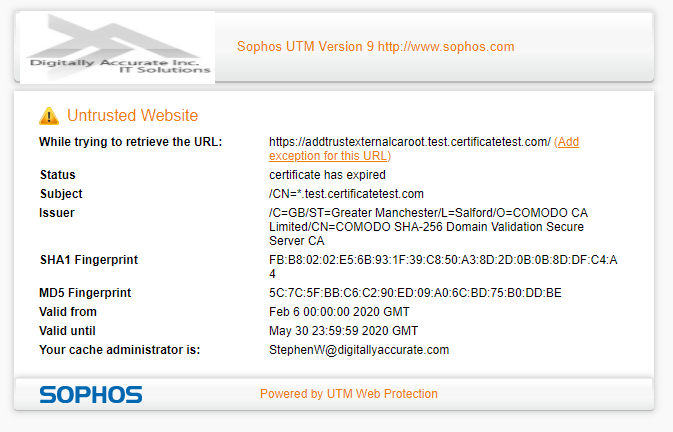
If you’re running a Sophos UTM firewall, you may start noticing websites not loading properly, or presenting an error reporting that a root CA has expired.
Sectigo COMODO CA Cetificate Untrusted Website Certificate has expired
Webpages that do not present an error may fail to load, or only load partial parts of the page.
Update June 3rd 2020 – There are reports that this issue is also occurring with other vendors security solutions as well (such as Palo Alto Firewalls).
The Issue
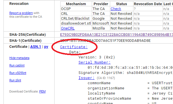
This is due to some root CA (Certificate Authority) certificates expiring.
Particularly this involves the following Root CA Certificates:
AddTrust AB – AddTrust External CA Root
The USERTRUST Network – USERTrust RSA Certification Authority
The USERTRUST Network – USERTrust ECC Certification Authority
So you want to add NVMe storage capability to your HPE Proliant DL360p Gen8 (or other Proliant Gen8 server) and don’t know where to start? Well, I was in the same situation until recently. However, after much research, a little bit of spending, I now have 8TB of NVMe storage in my HPE DL360p Gen8 Server thanks to the IOCREST IO-PEX40152.
Unsupported you say? Well, there are some of us who like to live life dangerously, there is also those of us with really cool homelabs. I like to think I’m the latter.
PLEASE NOTE: This is not a supported configuration. You’re doing this at your own risk. Also, note that consumer/prosumer NVME SSDs do not have PLP (Power Loss Prevention) technology. You should always use supported configurations and enterprise grade NVME SSDs in production environments.
Update – May 2nd 2021: Make sure you check out my other post where I install the IOCREST IO-PEX40152 in an HPE ML310e Gen8 v2 server for Version 2 of my NVMe Storage Server.
Update – June 21 2022: I’ve received numerous comments, chats, and questions about whether you can boot your server or computer using this method. Please note that this is all dependent on your server/computer, the BIOS/EFI, and capabilities of the system. In my specific scenario, I did not test booting since I was using the NVME drives purely as additional storage.
DISCLAIMER: If you attempt what I did in this post, you are doing it at your own risk. I won’t be held liable for any damages or issues.
NVMe Storage Server – Use Cases
There’s a number of reasons why you’d want to do this. Some of them include:
Server Storage
VMware Storage
VMware vSAN
Virtualized Storage (SDS as example)
VDI
Flash Cache
Special applications (database, high IO)
Adding NVMe capability
Well, after all that research I mentioned at the beginning of the post, I installed an IOCREST IO-PEX40152 inside of an HPE Proliant DL360p Gen8 to add NVMe capabilities to the server.
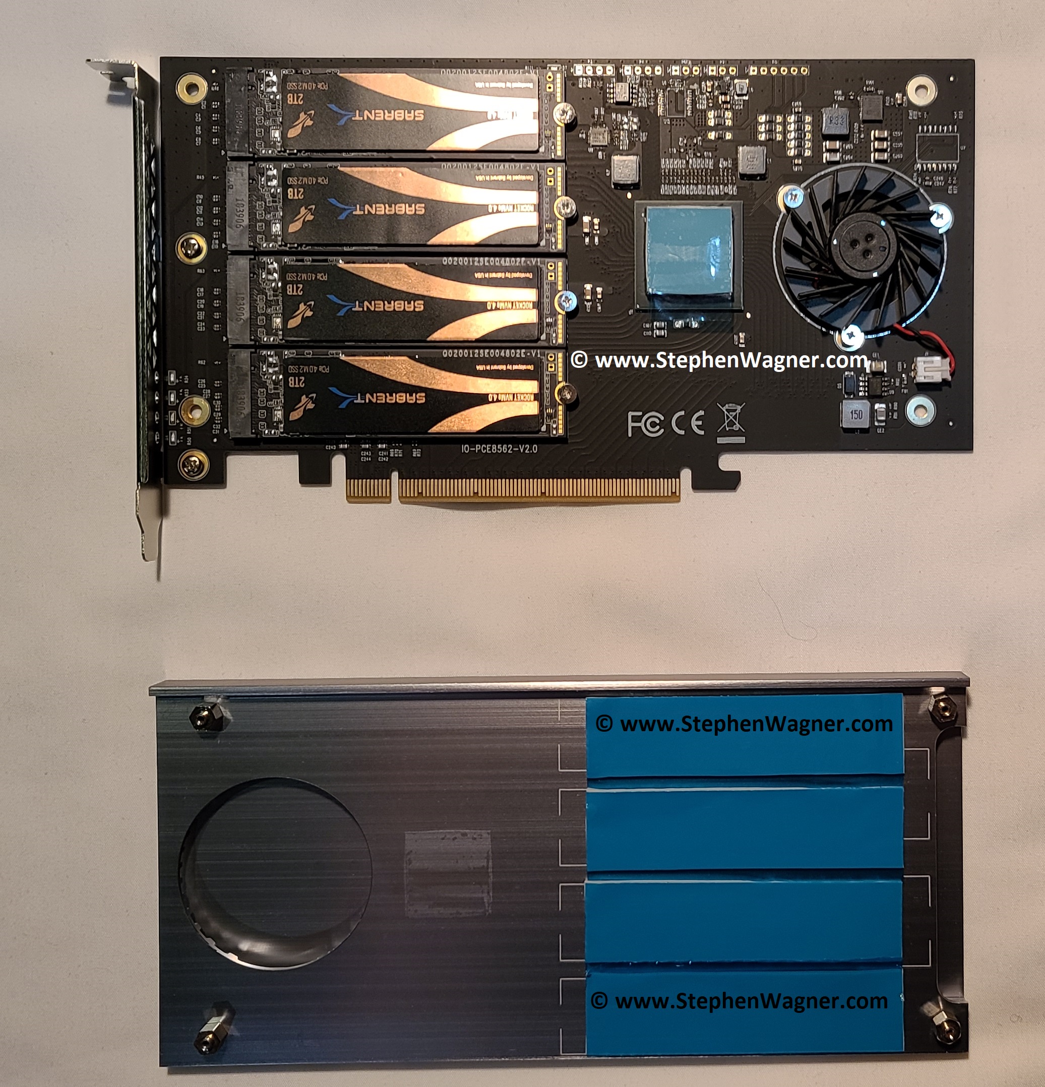
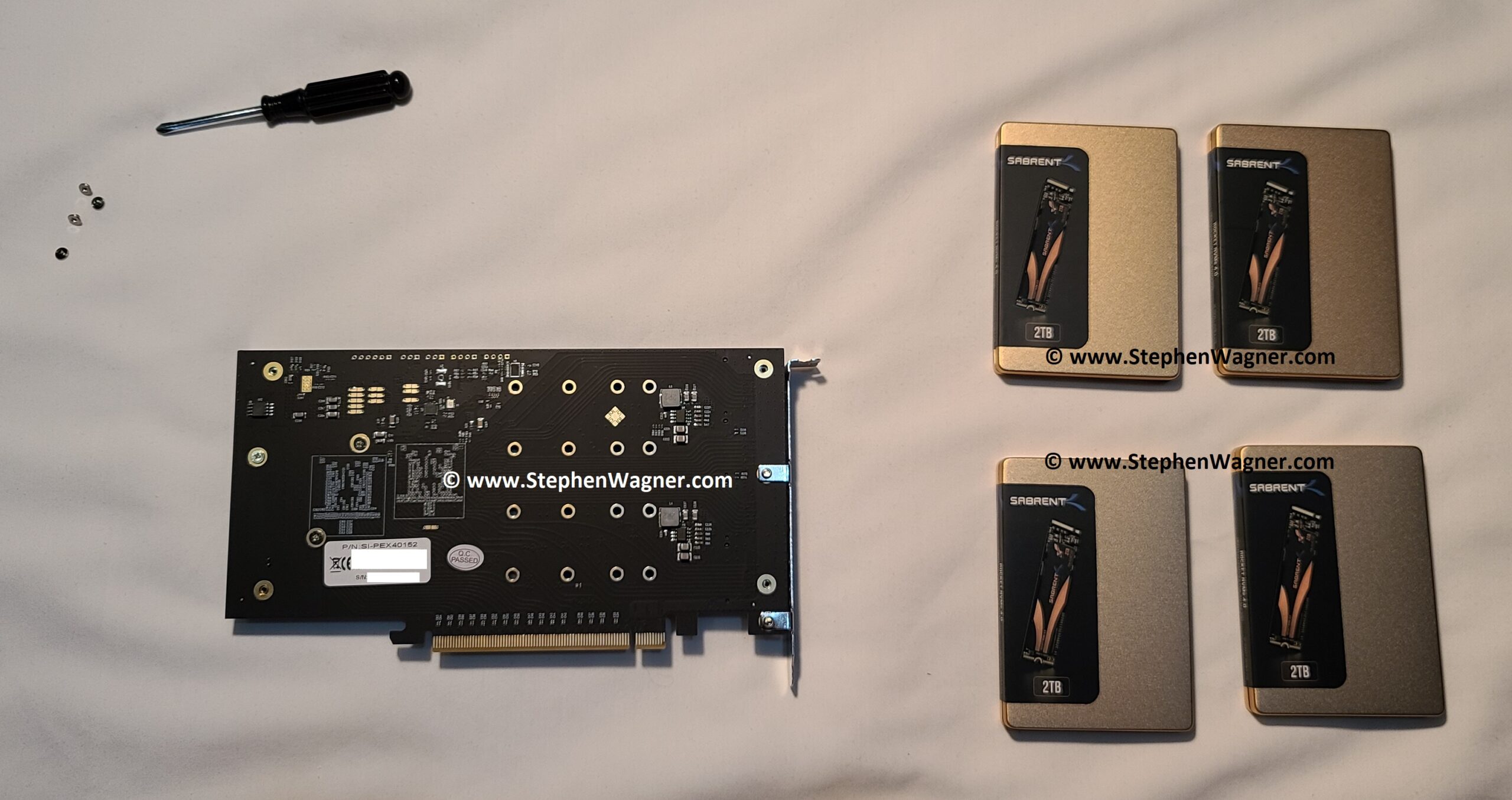
IOCREST IO-PEX40152 with 4 x 2TB Sabrent Rocket 4 NVME
At first I was concerned about dimensions as technically the card did fit, but technically it didn’t. I bought it anyways, along with 4 X 2TB Sabrent Rocket 4 NVMe SSDs.
The end result?
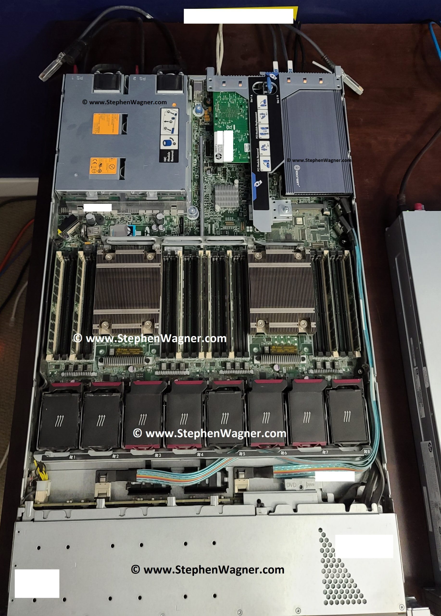
HPE DL360p Gen8 with NVME SSD
IMPORTANT: Due to the airflow of the server, I highly recommend disconnecting and removing the fan built in to the IO-PEX40152. The DL360p server will create more than enough airflow and could cause the fan to spin up, generate electricity, and damage the card and NVME SSD.
Also, do not attempt to install the case cover, additional modification is required (see below).
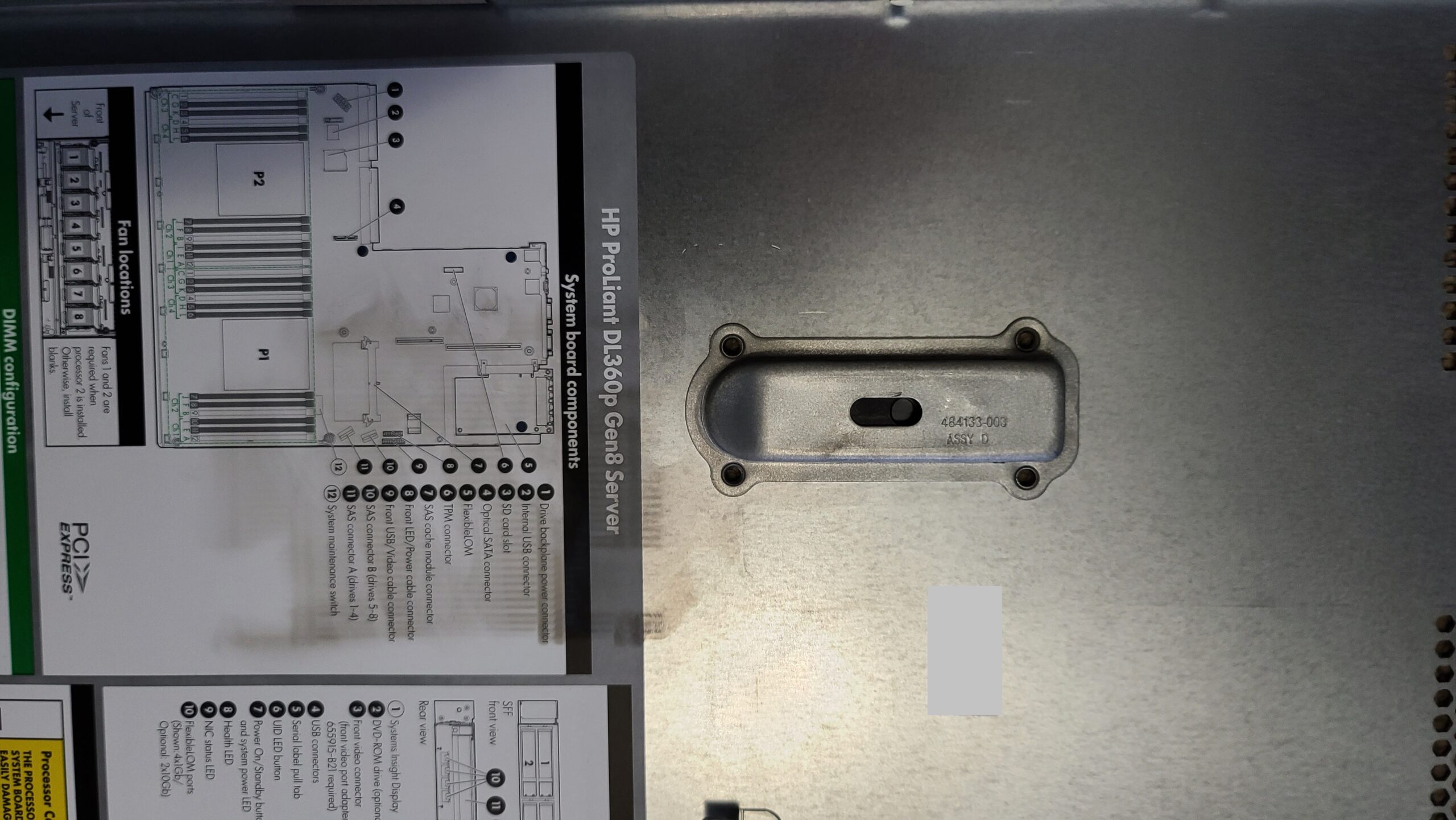
The Fit
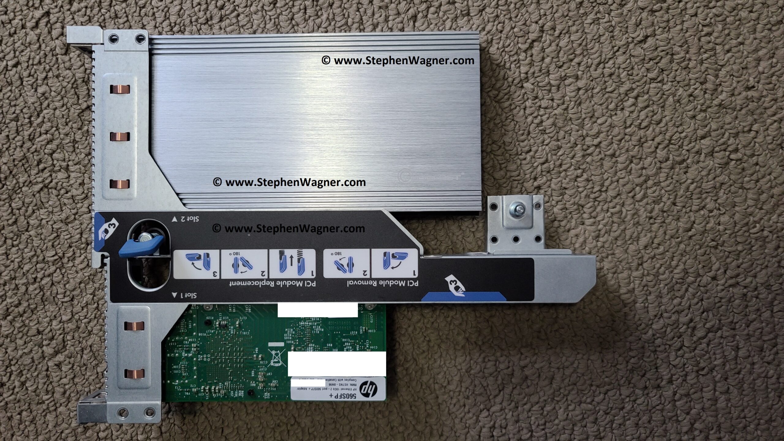
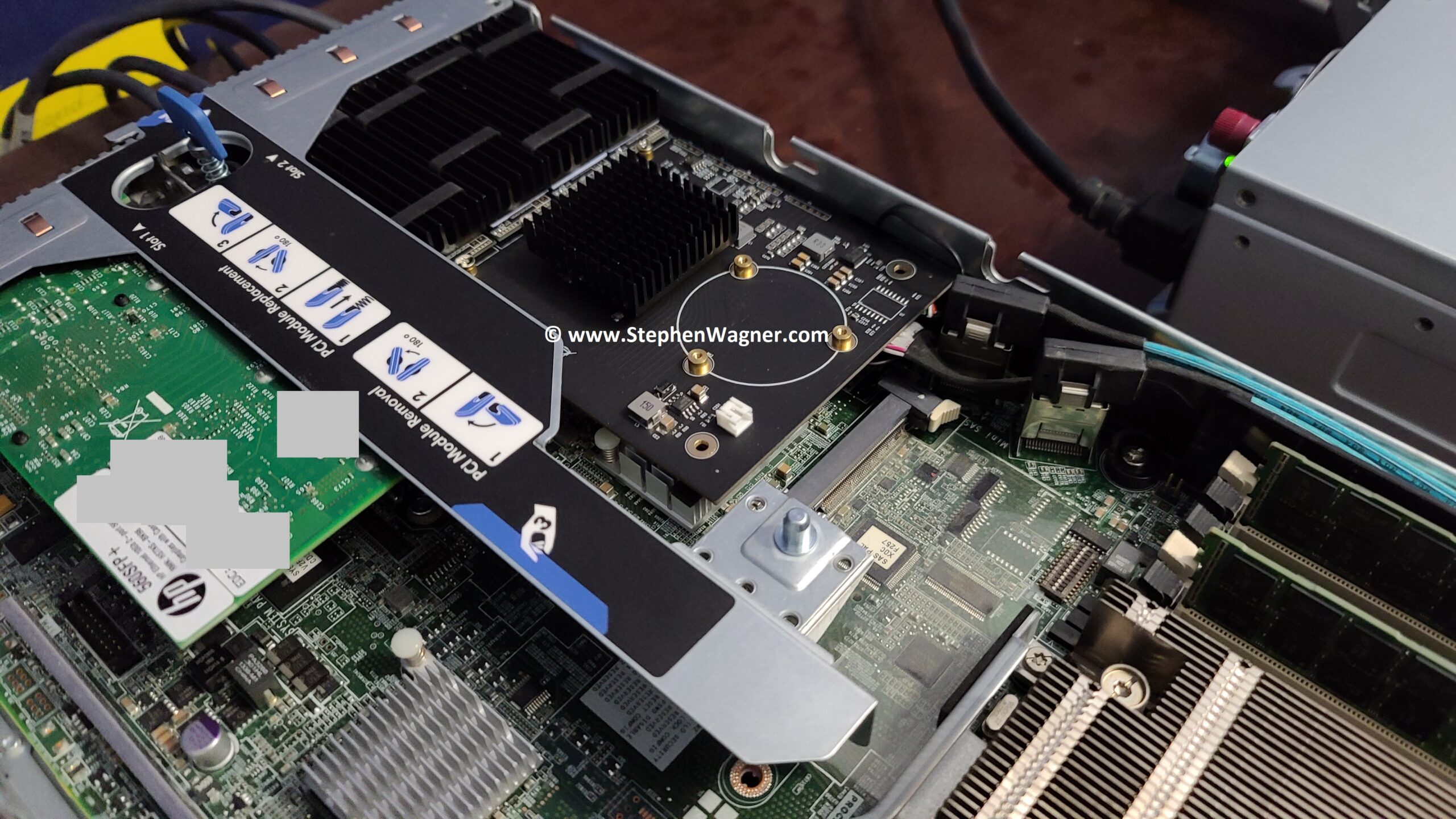
Installing the card inside of the PCIe riser was easy, but snug. The metal heatsink actually comes in to contact with the metal on the PCIe riser.
IO-PEX40152 installed on DL360p PCIe Riser
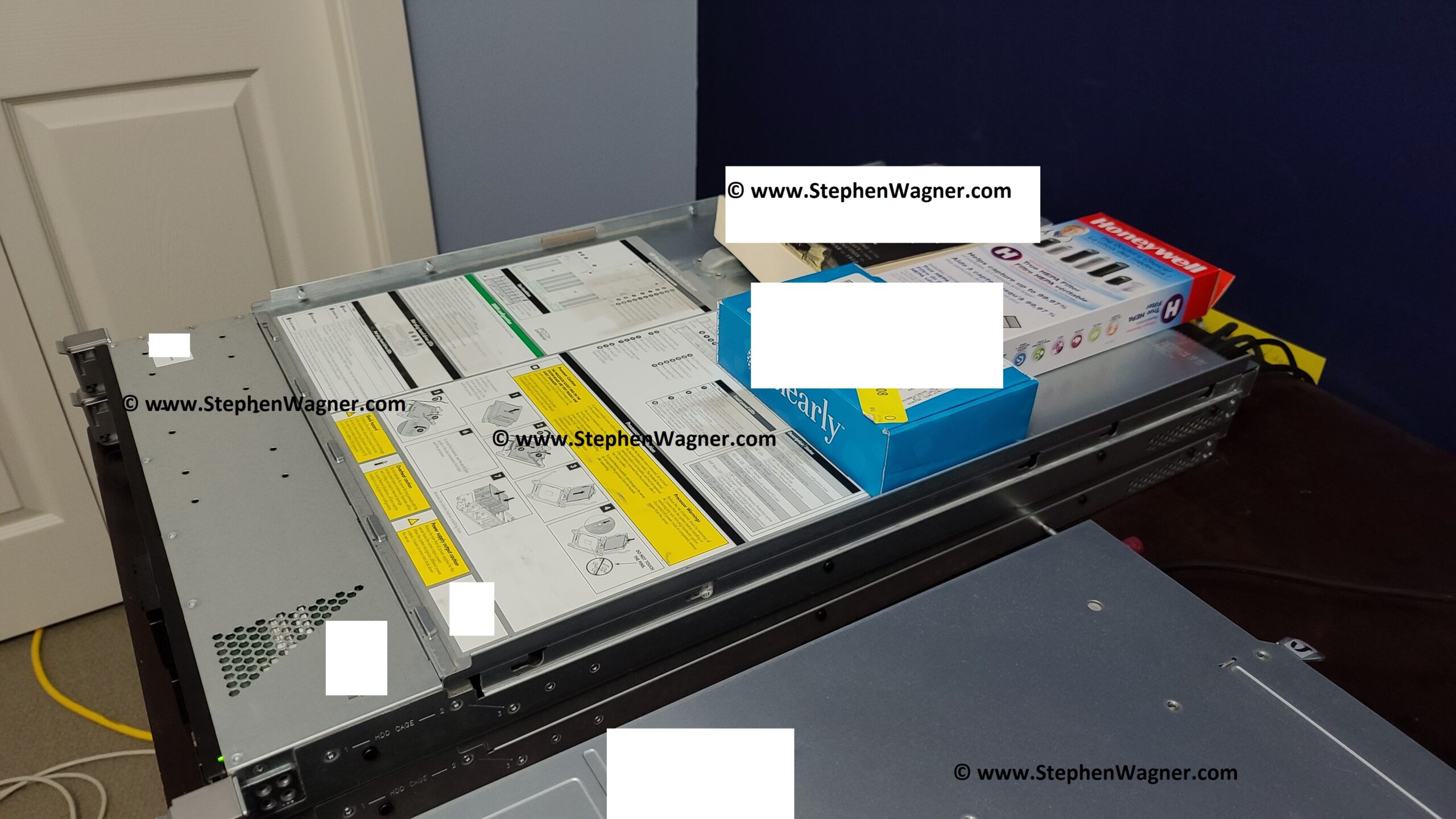
You’ll notice how the card just barely fits inside of the 1U server. Some effort needs to be put in to get it installed properly.
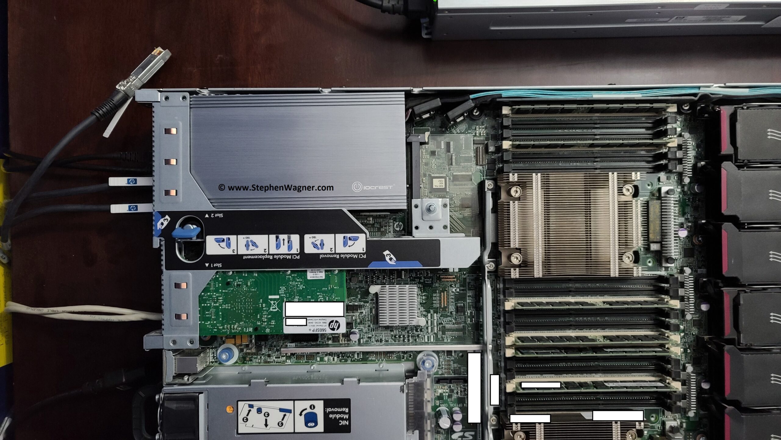
HPE DL360p Gen8 with IO-PEX40152 Installed
There are ribbon cables (and plastic fittings) directly where the end of the card goes, so you need to gently push these down and push cables to the side where there’s a small amount of thin room available.
We can’t put the case back on… Yet!
Unfortunately, just when I thought I was in the clear, I realized the case of the server cannot be installed. The metal bracket and locking mechanism on the case cover needs the space where a portion of the heatsink goes. Attempting to install this will cause it to hit the card.
HPE DL360p Gen8 Case Locking Mechanism
The above photo shows the locking mechanism protruding out of the case cover. This will hit the card (with the IOCREST IO-PEX40152 heatsink installed). If the heatsink is removed, the case might gently touch the card in it’s unlocked and recessed position, but from my measurements clears the card when locked fully and fully closed.
I had to come up with a temporary fix while I figure out what to do. Flip the lid and weight it down.
HPE DL360p Gen8 case cover upside down
For stability and other tests, I simply put the case cover on upside down and weighed it down with weights. Cooling is working great and even under high load I haven’t seen the SSD’s go above 38 Celsius.
The plan moving forward was to remove the IO-PEX40152 heatsink, and install individual heatsinks on the NVME SSD as well as the PEX PCIe switch chip. This should clear up enough room for the case cover to be installed properly.
The fix
I went on to Amazon and purchased the following items:
IOCREST IO-PEX40152 with GLOTRENDS M.2 NVMe SSD Heatsink on Sabrent Rocket 4 NVME
And now we install it in the DL360p Gen8 PCIe riser and install it in to the server.
You’ll notice it’s a nice fit! I had to compress some of the heat conductive goo on the PFX chip heatsink as the heatsink was slightly too high by 1/16th of an inch. After doing this it fit nicely.
Also, note the one of the cable/ribbon connectors by the SAS connections. I re-routed on of the cables between the SAS connectors they could be folded and lay under the card instead of pushing straight up in to the end of the card.
As I mentioned above, the locking mechanism on the case cover may come in to contact with the bottom of the IOCREST card when it’s in the unlocked and recessed position. With this setup, do not unlock the case or open the case when the server is running/plugged in as it may short the board. I have confirmed when it’s closed and locked, it clears the card. To avoid “accidents” I may come up with a non-conductive cover for the chips it hits (to the left of the fan connector on the card in the image).
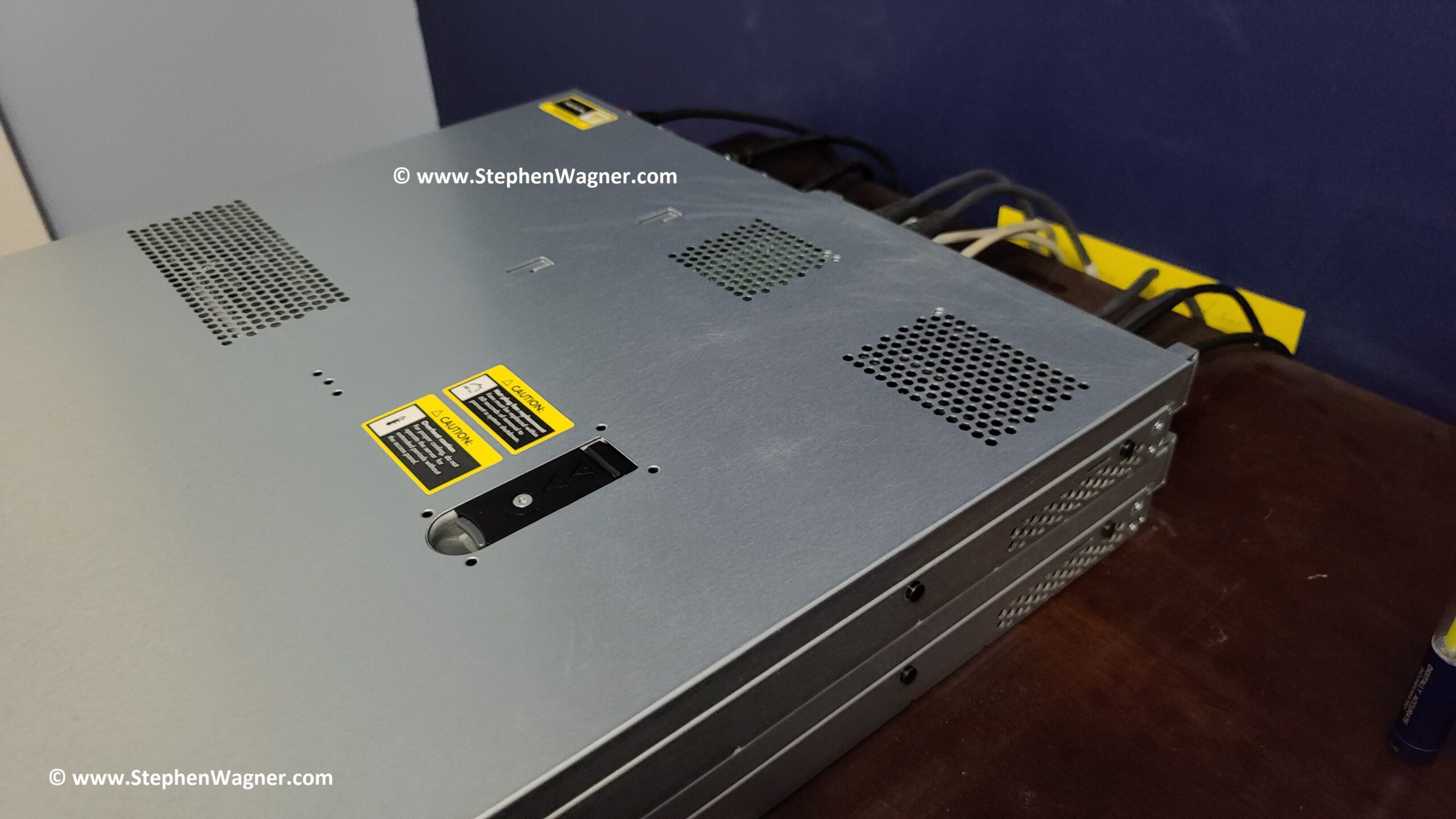
And with that, we’ve closed the case on this project…
HPE DL360p Gen8 Case Closed
One interesting thing to note is that the NVME SSD are running around 4-6 Celsius cooler post-modification with custom heatsinks than with the stock heatsink. I believe this is due to the awesome airflow achieved in the Proliant DL360 servers.
Conclusion
I’ve been running this configuration for 6 days now stress-testing and it’s been working great. With the server running VMware ESXi 6.5 U3, I am able to passthrough the individual NVME SSD to virtual machines. Best of all, installing this card did not cause the fans to spin up which is often the case when using non-HPE PCIe cards.
This is the perfect mod to add NVME storage to your server, or even try out technology like VMware vSAN. I have a number of cool projects coming up using this that I’m excited to share.
Looking to add quad (4) NVMe SSDs to your system and don’t have the M.2 slots or a motherboard that supports bifurcation? The IOCREST IO-PEX40152 QUAD NVMe PCIe card, is the card for you!
The IO-PEX40152 PCIe card allows you to add 4 NVMe SSDs to a computer, workstation, or server that has an available PCIe x16 slot. This card has a built in PEX PCIe switch chip, so your motherboard does not need to support bifurcation. This card can essentially be installed and used in any system with a free x16 slot.
This card is also available under the PART# SI-PEX40152.
In this post I’ll be reviewing the IOCREST IO-PEX40152, providing information on how to buy, benchmarks, installation, configuration and more! I’ve also posted tons of pics for your viewing pleasure. I installed this card in an HPE DL360p Gen8 server to add NVME capabilities to create an NVMe based Storage Server.
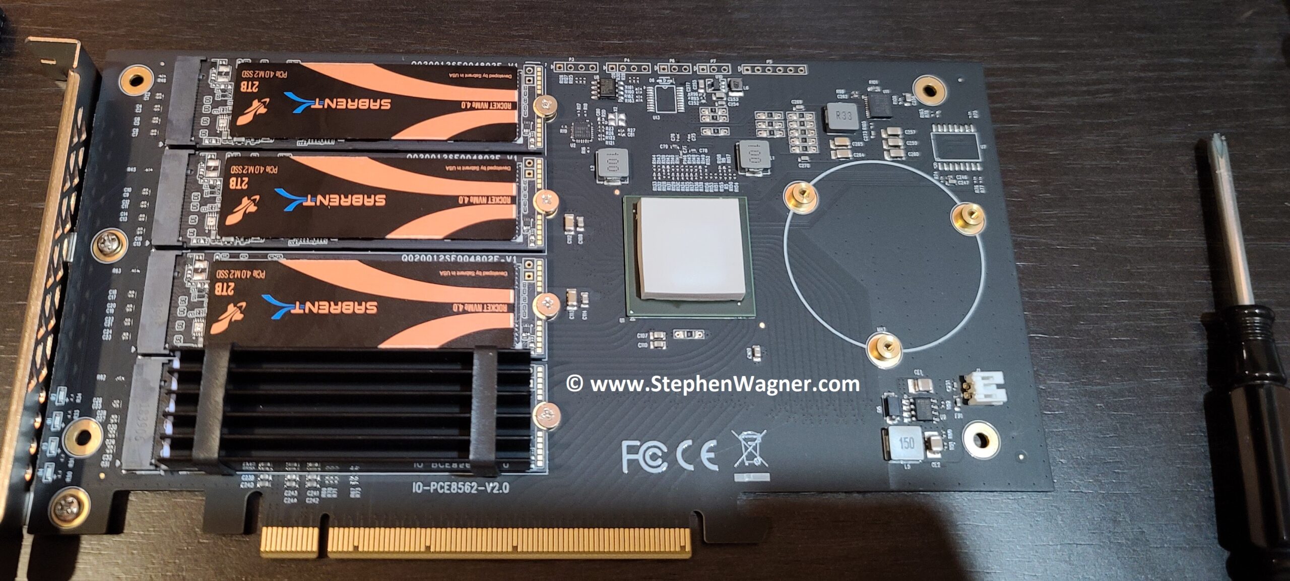
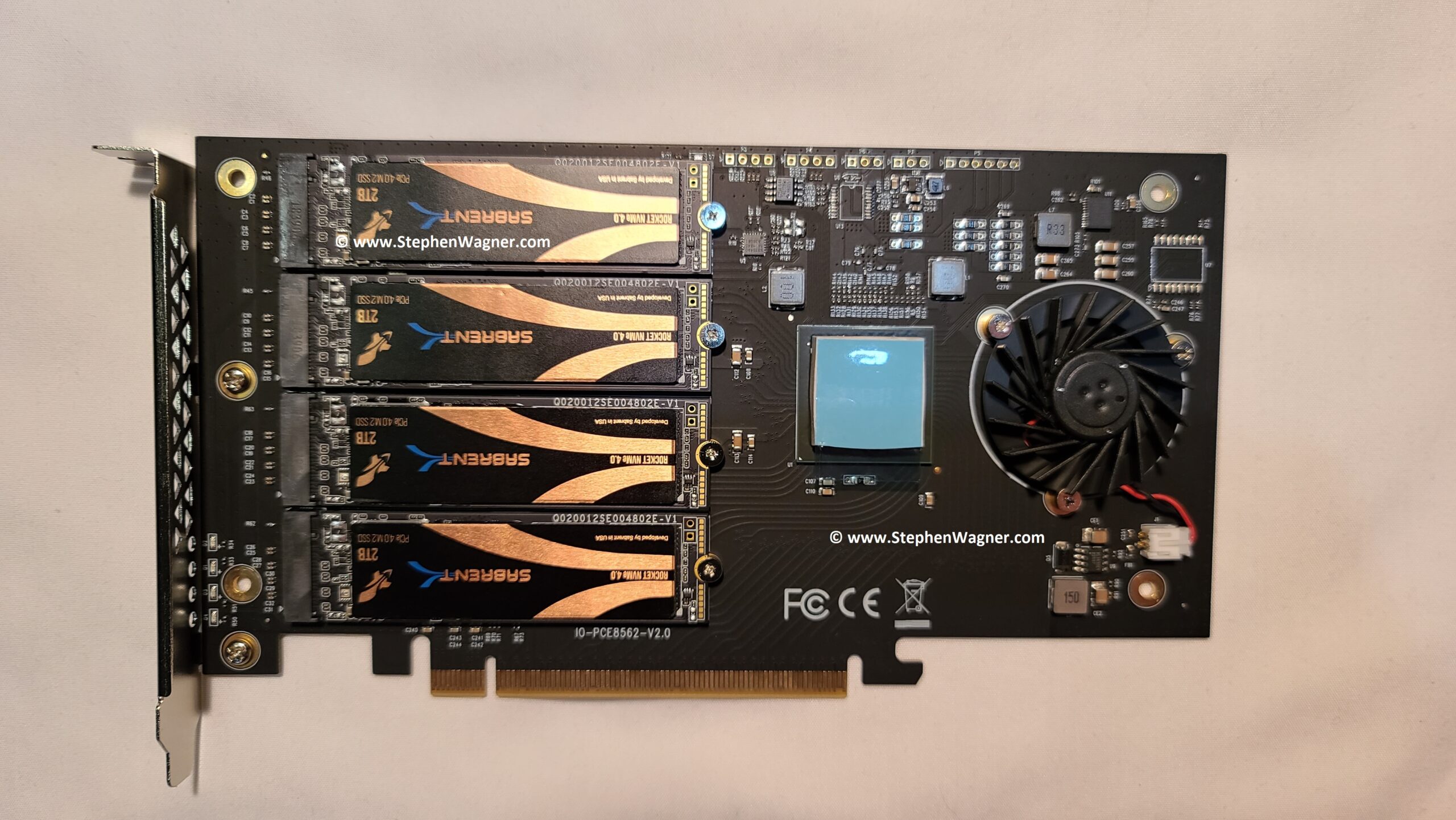
We’ll be using and reviewing this card populated with 4 x Sabrent Rocket 4 PCIe NVMe SSD, you can see the review on those SSD’s individually here.
IOCREST IO-PEX40152 PCIe Card loaded with 4 x Sabrent Rocket 4 2TB NVMe SSD
Why and How I purchased the card
Originally I purchased this card for a couple of special and interesting projects I’m working on for the blog and my homelab. I needed a card that provided high density NVME flash storage, but didn’t require bifurcation as I planned on using it on a motherboard that didn’t support 4/4/4/4 bifurcation.
By choosing this specific card, I could also use it in any other system that had an available x16 PCIe slot.
I considered many other cards (such as some from SuperMicro and Intel), but in the end chose this one as it seemed most likely to work for my application. The choices from SuperMicro and Intel looked like they are designed to be use on their own systems.
I purchased the IO-PEX40152 from the IOCREST AliExpress store (after verifying it was their genuine online store) and they had the most cost-effective price out of the 4 sources.
They shipped the card with FedEx International Priority, so I received it within a week. Super fast shipping and it was packed perfectly!
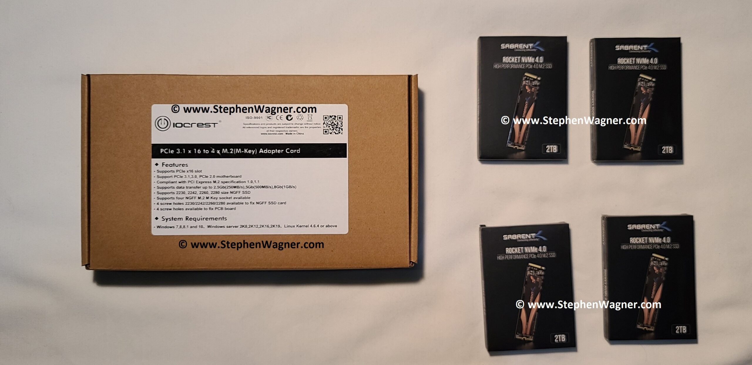
IOCREST IO-PEX40152 Box
Where to buy the IO-PEX40152
I found 3 different sources to purchase the IO-PEX40152 from:
Note that Syba USA is selling the IO-PEX40152 as the SI-PEX40152. The card I actually received has branding that identifies it both as an IO-PEX40152 and an SI-PEX40152.
As I mentioned above, I purchased it from the IOCREST AliExpress Online Store for around $299.00USD. From Amazon, the card was around $317.65USD.
IO-PEX40152 Specifications
Now let’s talk about the technical specifications of the card.
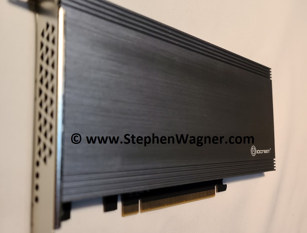
IO-PEX40152 Side Shot
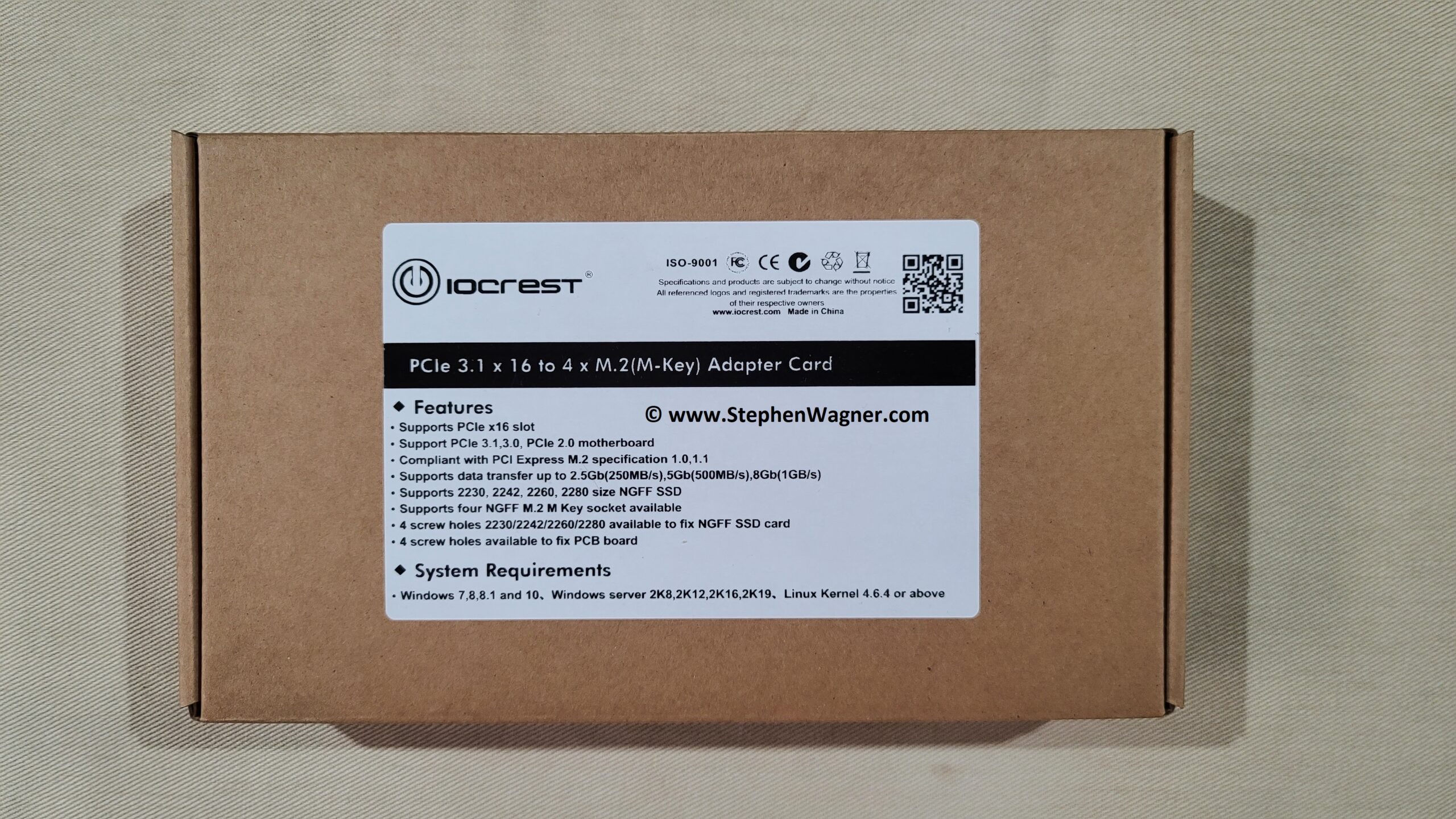
According to the packaging, the IO-PEX40152 features the following:
Installation in a PCIe x16 slot
Supports PCIe 3.1, 3.0, 2.0
Compliant with PCI Express M.2 specification 1.0, 1.2
Supports data transfer up to 2.5Gb (250MB/sec), 5Gb (500MB/sec), 8Gb (1GB/sec)
Supports 2230, 2242, 2260, 2280 size NGFF SSD
Supports four (4) NGFF M.2 M Key sockets
4 screw holes 2230/2242/2260/2280 available to fix NGFF SSD card
4 screw holes available to fix PCB board to heatsink
Supports Windows 10 (and 7, 8, 8.1)
Supports Windows Server 2019 (and 2008, 2012, 2016)
Supports Linux (Kernel version 4.6.4 or above)
While this list of features and specs are listed on the website and packaging, I’m not sure how accurate some of these statements are (in a good way), I’ll cover that more later in the post.
What’s included in the packaging?
1 x IO-PEX40152 PCIe x 16 to 4 x M.2(M-Key) card
1 x User Manual
1 x M.2 Mounting material
1 x Screwdriver
5 x self-adhesive thermal pad
They also note that contents may vary depending on country and market.
Unboxing, Installation, and Configuration
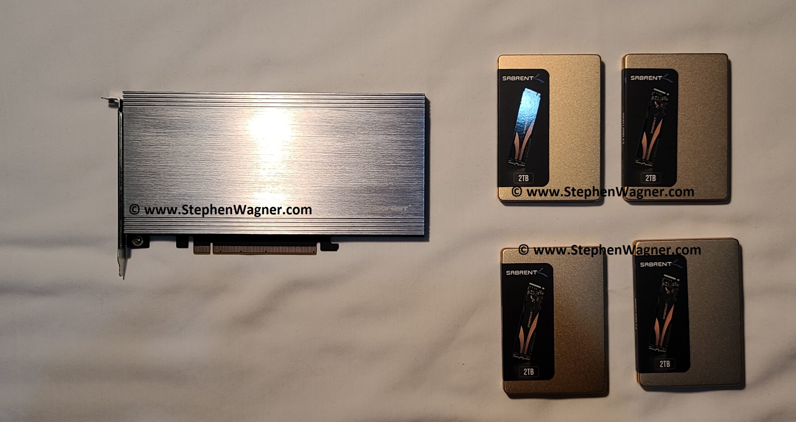
As menitoned above, our build includes:
1 x IOCREST IO-PEX40152
4 x Sabrent Rocket 4 NVMe PCIe NVMe SSD
IO-PEX40152 Unboxing with 4 x Sabrent Rocket 4 NVMe 2TB SSD
Picture of IO-PEX40152 with 4 x Sabrent Rocket 4 NVMe 2TB SSD
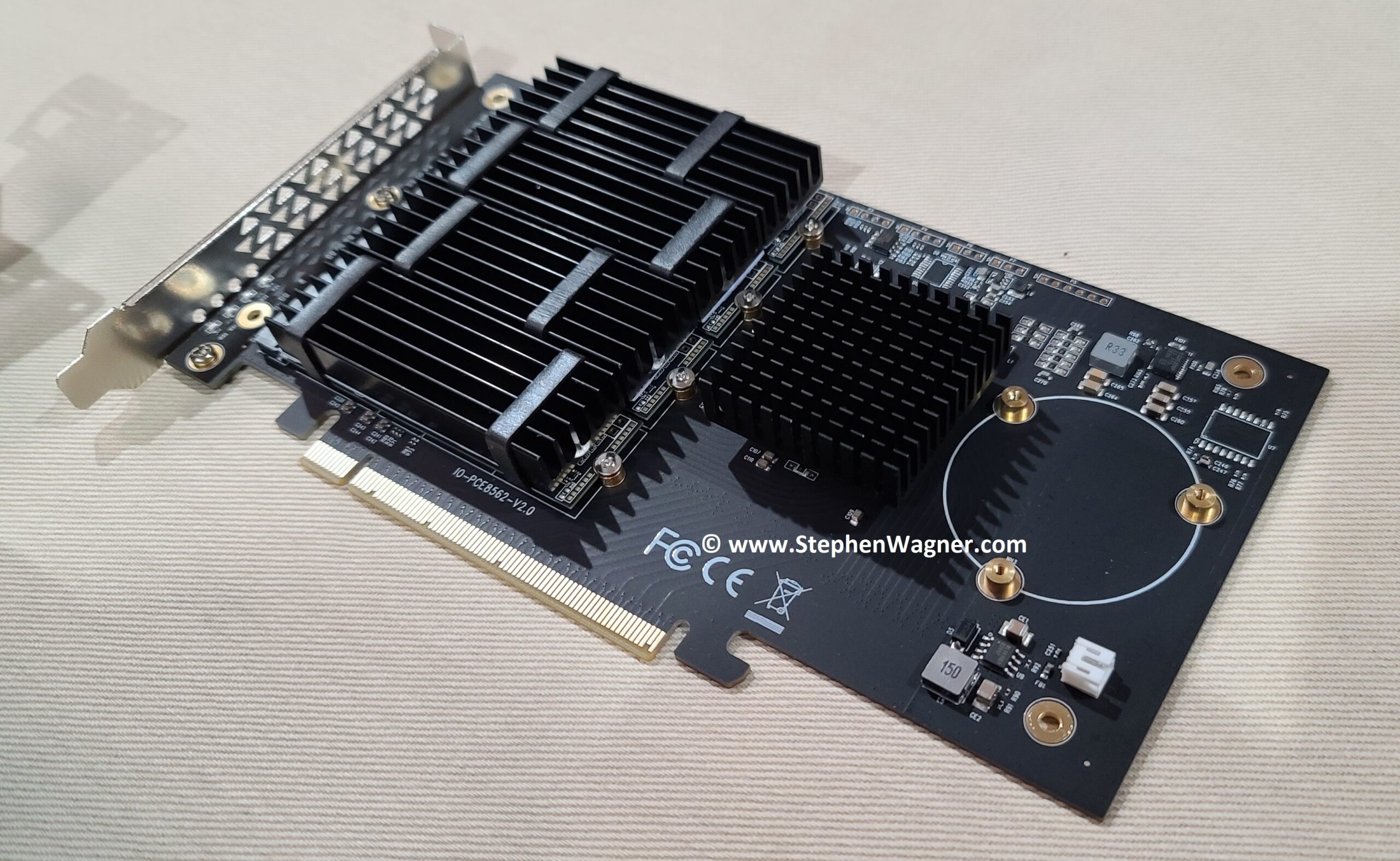
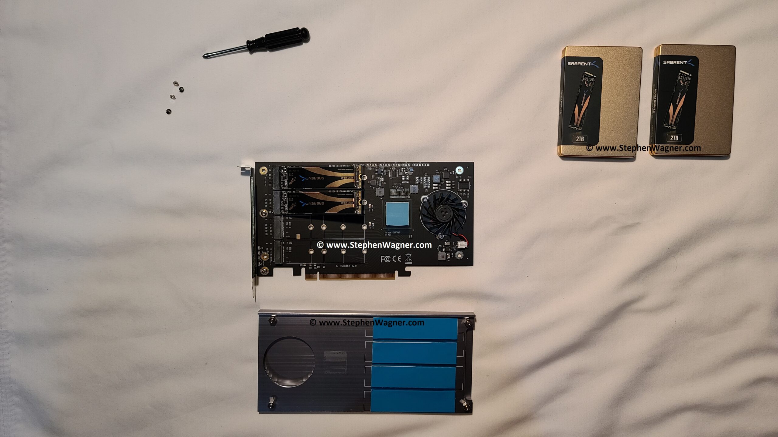
You’ll notice it’s a very sleek looking card. The heatsink is beefy, heavy, and very metal (duh)! The card is printed on a nice black PCB.
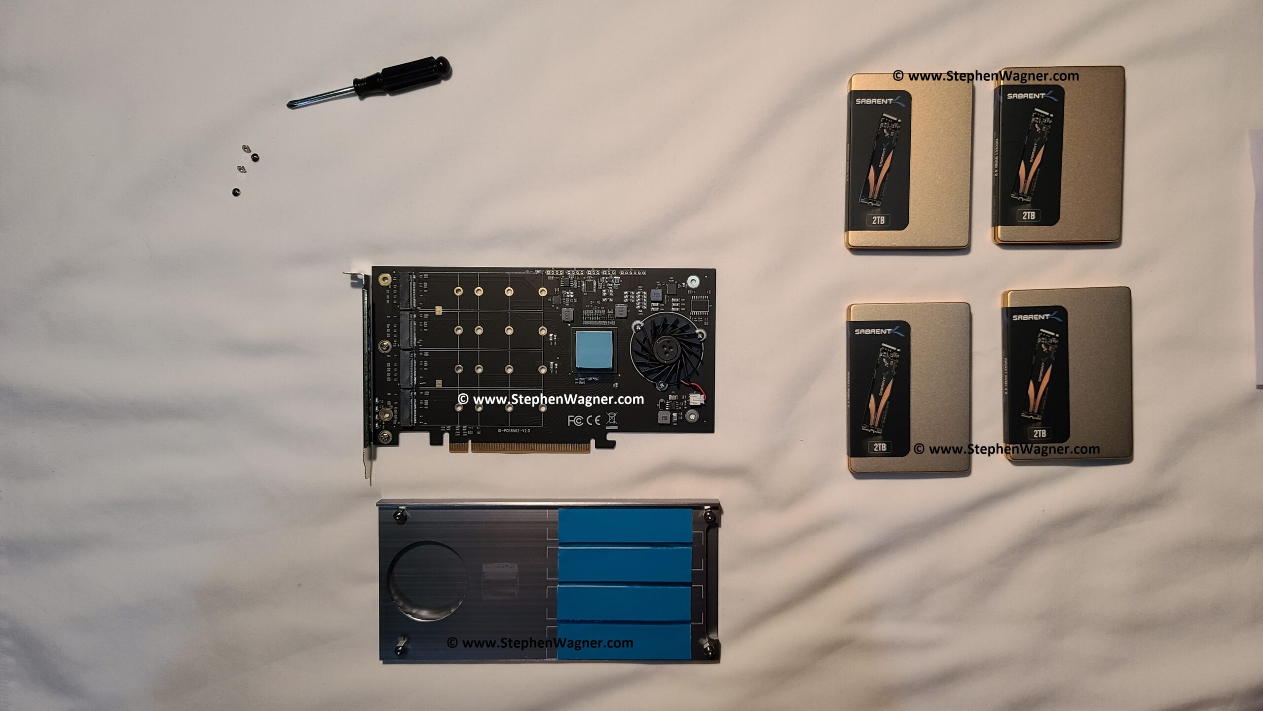
Removing the 4 screws to release the heatsink, we see the card and thermal paste pads. You’ll notice the PCIe switch chip.
IOCREST IO-PEX40152 Frontside of card
And the backside of the card.
IOCREST IO-PEX40152 Backside of card
NVMe Installation
I start to install the Sabrent Rocket 4 NVMe 2TB SSD.
IO-PEX40152 with 2 SSD populated
IOCREST IO-PEX40152 PCIe Card loaded with 4 x Sabrent Rocket 4 2TB NVMe SSD
That’s a good looking 8TB of NVMe SSD!
Note that the cards will wiggle side to side and have play until screw is tightened. Do not over-tighten the screw!
Make sure before installing the heatsink cover that you remove the blue plastic film on the heat transfer material between NVME and heatsink, and the PEX chip and heatsink.
After that, I installed it in the server and was ready to go!
Heatsink and cooling
A quick note on the heatsink and cooling…
While the heatsink and cooling solution it comes with works amazing, you have flexibility if need be to run and operate the card without the heatsink and fan (the fan doesn’t cause any warnings if disconnected). This works out great if you want to use your own cooling solution, or need to use this card in a system where there isn’t much space. The fan can be removed by removing the screws and disconnecting the power connector.
Note, after installing the NVME SSD, and you affix the heatsink, in the future you will notice that the heatsink get’s stuck to the cards if you try to remove it at a later date. If you do need to remove the heatsink, be very patient and careful, and slowly remove the heatsink to avoid damaging or cracking the NVME SSD and the PCIe card itself.
Speedtest and benchmark
Let’s get to one of the best parts of this review, using the card!
Unfortunately due to circumstances I won’t get in to, I only had access to a rack server to test the card. The server was running VMware vSphere and ESXi 6.5 U3.
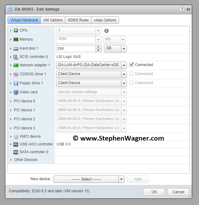
After shutting down the server, installing the card, and powering on, you could see the NVMe SSD appearing as available to PCI Passthrough to the VMs. I enabled passthrough and restarted again. I then added the individual 4 NVME drives as PCI passthrough devices to the VM.
IO-PEX40152 PCI Passthrough on VMware vSphere and ESXi
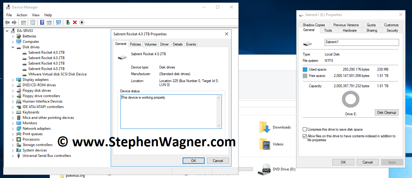
Turning on the system, we are presented with the NVMe drives inside of the “Device Manager” on Windows Server 2016.
IOCREST IO-PEX40152 presenting 4 Sabrent NVME to Windows Server 2016
Now that was easy! Everything’s working perfectly…
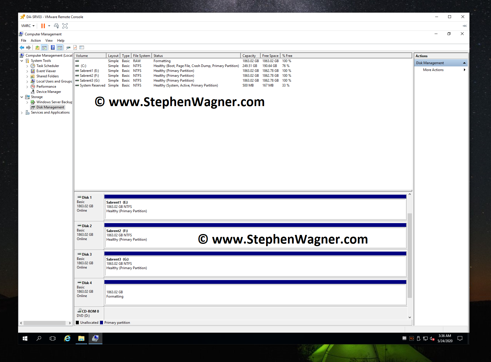
Now we need to go in to disk manager and create some volumes for some quick speed tests and benchmarks.
Windows Server 2016 Disk Manager with IOCREST IO-PEX40152 and Sabrent Rocket 4 NVME SSD
Again, no problems and very quick!
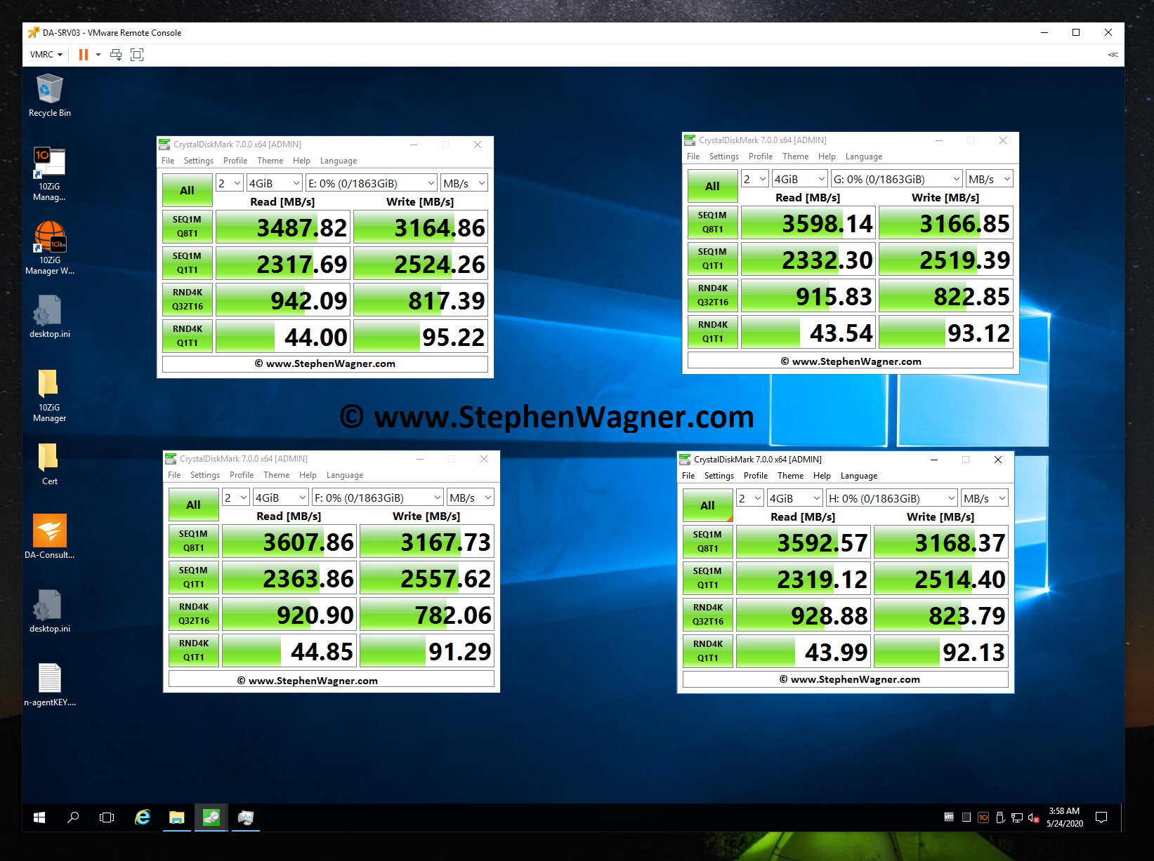
Let’s load up CrystalDiskMark and test the speed and IOPS!
CrystalDiskMark testing an IOCREST IO-PEX40152 and Sabrent Rocket 4 NVME SSD
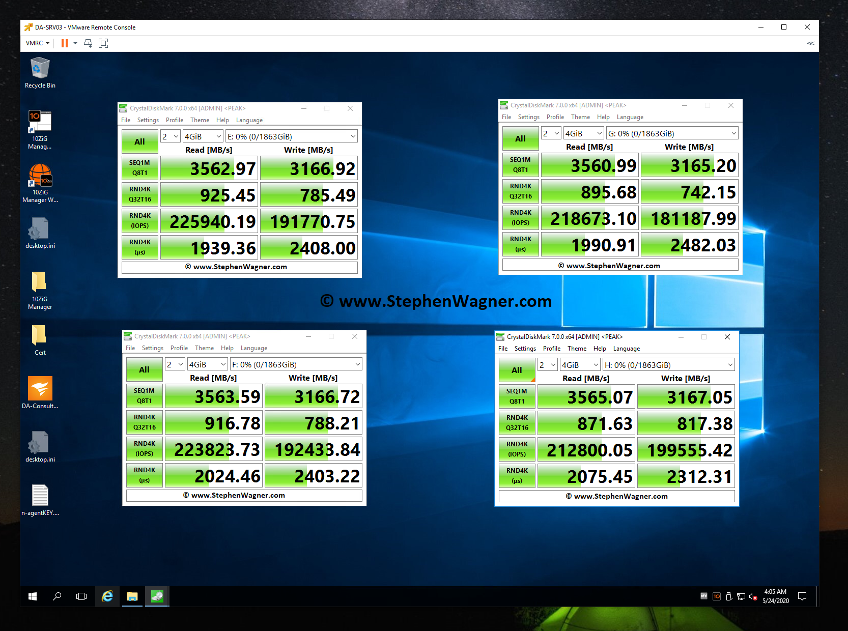
CrystalDiskMark testing IOPS on an IOCREST IO-PEX40152 and Sabrent Rocket 4 NVME SSD
What’s interesting is that I was able to achieve much higher speeds using this card in an older system, than directly installing one of the SSDs in a new HP Z240 workstation. However, unfortunately due to CPU limitations (maxing the CPU out) of this server used above, I could not fully test, max out, or benchmark the IOPS on an individual SSD.
Additional Notes on the IO-PEX40152
Some additional notes I have on the IO-PEX40152:
The card works perfectly with VMware ESXi PCI passthrough when passing it through to a virtualized VM.
The card according to the specifications states a data transfer up to 1GB/sec, however I achieved over 3GB/sec using the Sabrent Rocket 4 NVME SSD.
While the specifications and features state it supports NVME spec 1.0 and 1.1, I don’t see why it wouldn’t support the newer specifications as it’s simply a PCIe switch which NVMe slots.
Conclusion
This is a fantastic card that you can use reliably if you have a system with a free x16 slot. Because of the fact it has a built in PCIe switch and doesn’t require PCIe bifurcation, you can confidently use it knowing it will work.
I’m looking forward to buying a couple more of these for some special applications and projects I have lined up, stay tuned for those!
This website uses cookies to improve your experience. We'll assume you're ok with this, but you can opt-out if you wish.
Do you accept the use of cookies and accept our privacy policy? AcceptRejectCookie and Privacy Policy
Privacy & Cookies Policy
Privacy Overview
This website uses cookies to improve your experience while you navigate through the website. Out of these cookies, the cookies that are categorized as necessary are stored on your browser as they are essential for the working of basic functionalities of the website. We also use third-party cookies that help us analyze and understand how you use this website. These cookies will be stored in your browser only with your consent. You also have the option to opt-out of these cookies. But opting out of some of these cookies may have an effect on your browsing experience.